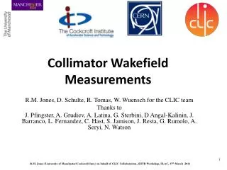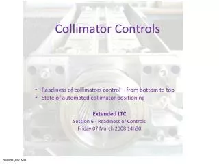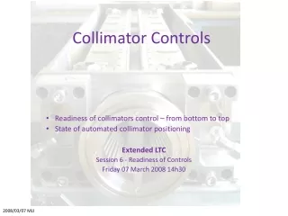
Collimator Design
Collimator Design. Adriana Bungau The University of Manchester, UK. Annual EuroTev meeting - Frascati, Italy, 23 - 25 January 2008. Content. Introduction - SWMD collaboration - Collimator design - requirements Wakefield Measurements at SLAC-ESA

Collimator Design
E N D
Presentation Transcript
Collimator Design Adriana Bungau The University of Manchester, UK Annual EuroTev meeting - Frascati, Italy, 23 - 25 January 2008
Content • Introduction • - SWMD collaboration • - Collimator design - requirements • Wakefield Measurements at SLAC-ESA • - T480 experiment (collimators, beam parameters) • - data analysis • Collimator Damage Tests at ATF • - test plan • - schedulle • - test equipment • - Conclusion
People - SWMD collaboration Birmingham: N.Watson, M Slater SFTF: L.Fernandez, G.Ellwood, J.Greenhalgh, B.Fell, S. Appleton CERN: G.Rumolo, D.Schulte, A.Latina Lancaster: D.Burton, J.Smith, R.Tucker Manchester: R.Barlow, A.Bungau, R.Jones Darmstadt: M.Karkkainen, W.Muller, T.Weiland Also: a strong collaboration with SLAC (S.Molloy and M.Woods) for wakefield beam tests and KEK for collimator damage.
Requirements • Significant problems: • short-range wakefields ->lead to emittance dilution and beam jitter at the IP • impact of a no of high density bunches can damage the spoilers 20 mrad 1. Spoiler geometry must reduce the wakefields to an acceptable level - long, shallow tapers of ~20 mrad, - short flat upper section of 0.6 r.l. - high conductivity surface coating the wakefield aspects of the design are addressed by experimental work centered around T480 project at SLAC-ESA and simulations with Gdfidl, Echo, Merlin, Placet (see Daniel’s talk) 2. Spoilers are required to survive 1 bunch at 250 and 2 bunches at 500 GeV - use bulk material to minimise fractures, stress but optimal for heat flow - long path length for errant beams striking spoilers (large r.l : graphite, beryllium etc) the design approach consider simulations with FLUKA, Geant4, EGS4, ANSYS and experimental work at KEK 0.6 r.l
Wakefield tests at SLAC-ESA Aim: measure the beam kick and compare it with theoretical predictions and simulations Beam Parameters at SLAC ESA and ILC Beam size: 100 um vertically 0.5-1.5 mm longitudinally
T480 “wakefield box” ESA beamline ESA beamline
Wakefield Box • readings from each BPM were recorded together with the bunch charge and energy • the kick was determined by performing a straight line fit to the upstream BPM and a separate one to fit the downstream ones • the kick was calculated as the difference in the slopes of these fits
a = 166 mrad r = 1.4 mm Col. 12 T480 (prelim.) 2007 data Angular kick (V/pC) Collimator y (mm) Data analysis Luis Fernandez - Daresbury
a = 166 mrad r = 1.4 mm Col. 12 L=1000 mm a = 324 mrad r = 2 mm Col. 1 a = 166 r = 1.4 mm (r = ½ gap) Col. 6 Col. 3 a = 324 mrad r = 1.4 mm Luis Fernandez - Daresbury
Measured and calculated kick factor Note: quoted errors are estimates
Collimator Damage Experiment at ATF
Previous simulations Aim: the collimators can be damaged by the impact of several bunches Luis Fernandez - DL
Stress wave George Ellwood - RAL
Purpose of the ATF test • First run at ATF • commisioning of the vacuum vessel, multi-axis mover, beam position and size monitors • validate the mode of operation required for ATF tests • measurement of the size of the damage region after individual beam impacts on test target (validation of FLUKA/ANSYS simulations of properties of material) • ensure that the radiation protection requirements can be satisfied • Next phase at ATF2 • measure the shock waves within the sample (VISAR or LDV) for single bunch and multiple bunches at ~ILC bunch spacing
ATF Schedule February: 1st week - mover commisioning at RAL 2nd week - installation at KEK 3rd week - testing readout of beamline instrumentation 4th week - measurement of samples - shock wave measurements are planned at ATF2
Sample Target • we would like to use a 100µm thick • Ti-6Al-4V sample. • the sample will probably be held • between knife edge grips, similar to • those illustrated. • we could leave the top of the sample • free from the grips. Grip Exposed edge of sample
3 1 2 y y y Move sample in X until beam is no longer in contact. No Signal from detector Move sample in Y until beam is in contact. Signal from detector. Beam does not touch sample. No signal from detector x x x Reference Location
4 y x Move sample in X & Y until sample is in required location. Increase charge to damage sample. Beam operation • Once the reference edge has been found we will use the VG manipulator to step the sample • a known distance in X and Y. • We will then increase the charge and try to damage the sample. • Then we will move the sample to a new location and try to damage with a different charge. • We will continue to do this until we have performed all the planned tests.
Fluka Predictions • after testing, we intend to measure the are of damage of each impact with a Scanning Electron Microscope • we will know the location of each damaged region because know the distance from the reference edge. • this will help validate our predictions on beam damage. Luis Fernandez - Daresbury
SWMD: Deliverable Summary “Engineering design for ILC mechanical spoiler, including prototype evaluations of wakefield and beam-damage performance.” • Wakefields: T480 at SLAC to evaluate wakefield performance of candidate spoiler designs, benchmarking calculations/modelling • 16 jaw designs studied • Beam damage: detailed simulations of beam damage to spoiler jaws, including transient shockwave effects • Achieved designs which satisfy beam damage requirements • Phase 1 of beam test to verify modelling, starts at ATF 18 Feb. 2008 • Outcome of ongoing wakefield optimisation likely to require further iteration on candidate designs • First conceptual design for mechanical spoiler design available, to report at EPAC’08.
SWMD: Deliverables Summary • Specification of requirements for LC spoilers - Complete • Eurotev Report 2006-015 and ILC RDR • Report on applicability of bench tests for ILC collimator design - Achieved • Initial report EPAC’06/EUROTeV Report 2006-056 • 2007 work method not suitable for quantitative tests of collimator jaws, had been identified as risk in EUROTeVAnnex I (amended). • Final report in preparation. • 3D simulation of wakefields for various candidate spoiler prototypes - Achieved • For 16 ESA collimators, most recently using non-conformal moving mesh GdfidL • Also for ECHO-3D at EPAC’06 • Additional mesh dependence studies ongoing, esp. for smallest sz • PAC’07, EPAC’06, EUROTeV-Reports 2006-055 (GdfidL) and 2006-103 (MAFIA) • Parametrised wakefield characteristics of spoilers for full simulation of the BDS • See COLSIM WP
SWMD: Deliverables Summary • Report on wakefield beam tests - Achieved • Analysis of 2007 and 2006 T480 data for publication in progress, including: • BPM uncertainties/calibrations, bunch length monitoring • Original plan was to use SCP and established instrumentation See PAC’07, EPAC’06, EUROTeV Reports 2007-044, 2006-059, 2006-060 • ECHO-3D: new code suitable for LC regime (long structures, short bunches), with predictions verified by experimental data • No public version so far • Report on spoiler damage estimates and comparison with test beam data – Partially achieved • Simulations carried out with Fluka, Geant4 (+EGS with Keller), see EPAC’06 and EUROTeV Reports 2006-015 and 2006-021 • FEA studies in ANSYS3D/Fluka of transient stress waves, see PAC’07, EPAC’06 • ATF beam test approved, see PAC’07, scheduled for run 18 Feb 2008 • Optimal spoiler design to achieve requirements – Partially achieved • We have designs for material and geometry which can satisfy beam damage requirements • Outcome of ongoing wakefield optimisation likely to require further iteration on candidate designs • First conceptual engineering design produced
Previous Simulations Made most detailed Simulations of spoiler jaw damage to date. beam beam collimator reflected shear waves heated zone beam compressive waves Reflected tensile waves Aim: quantify collimators damage from impact of several bunches Temperature increase from 1 bunch impact melting temp. Exceeds: fracture temp. Best candidate designs