Download
1 / 27
270 likes | 411 Vues
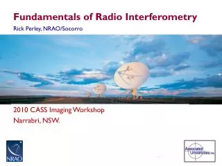
Lyle Hoffman, Lafayette College ALFALFA Undergraduate Workshop Arecibo Observatory, 2009 Jan. 12. Fundamentals of Radio Astronomy. Outline. Sources in brief Radiotelescope components Radiotelescope characteristics. Useful Texts. Burke & Graham-Smith, An Introduction to Radio Astronomy

E N D
Lyle Hoffman, Lafayette College ALFALFA Undergraduate Workshop Arecibo Observatory, 2009 Jan. 12 Fundamentals of Radio Astronomy
Outline • Sources in brief • Radiotelescope components • Radiotelescope characteristics Useful Texts Burke & Graham-Smith, An Introduction to Radio Astronomy Rohlfs, Tools of Radio Astronomy Stanimirovic et al., Single-dish Radio Astronomy: Techniques and Applications
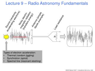
Sources of Radio Emission • Blackbody (thermal) • Continuum sources • Spectral line sources
Blackbody Sources • Peak in cm-wave radio requires very low temperature: mT = 0.2898 cm K • Cosmic Microwave Background is about the only relevant blackbody source • Ignored in most work – essentially constant source of static (same in all directions) and much weaker than static produced by instrumentation itself
Continuum Sources • Due to relativistic electrons: Synchrotron radiation Bremsstrahlung
Continuum Sources • Quasars, Active Galactic Nuclei, Pulsars, Supernova Remnants, etc. • Used by ALFALFA for calibration
Spectral Line Sources • Neutral hydrogen (H I ) spin-flip transition • Recombination lines (between high-lying atomic states) • Molecular lines (CO, OH, etc.)
Doppler effect: frequency shift of spectral line due to relative motion of source and observer • Closely related: redshift due to expansion of universe • Customarily report “velocity” as cz = c(l-l0)/lo = c(f0-f)/f0
H I spectral line from galaxy shifted by expansion of universe (“recession velocity”) and broadened by rotation Frequency
Radiotelescope Components • Reflector(s) • Feed horn(s) • Low-noise amplifier • Filter • Downconverter • IF Amplifier • Spectrometer
Feedhorns Typical cm-wave feedhorn 4 GHz feedhorn on LCRT
Signal Path Low-Noise Amplifier Down-converter Filter IF Amplifier Spectro-meter Local Oscil-lator
Autocorrelation Spectrometer • Special-purpose hardware computes autocorrelation function: Rn = 1N [(tj)(tj+nt)] where t is lag and is signal voltage; integer n ranges from 0 to (t f)-1 if frequency channels of width f are required • Power spectrum is discrete Fourier transform (FFT) of Rn
Nyquist theorem: must sample at rate 2B to achieve spectrum of bandwidth B without aliassing Diamonds: samples at rate ~B give aliassed signal near 0 Hz Ovals: samples at rate >2B give ~correct period
Radiotelescope Characteristics • Gain & effective area • Beam, sidelobes, stray radiation • Sensitivity, noise & integration time • Polarization & Stoke’s parameters
Gain & effective area • Received power Prec • Flux (energy per unit area per unit time) S • Effective area Aeff = Prec / S • Gain G for transmitter is ratio of emitted flux in given direction to P/(4r2) • Most emitted (received) within central diffraction max, angle ~ / D • So G = 4Aeff / 2
Beam & sidelobes • Essentially diffraction pattern of telescope functioning as transmitter • Uniformly illuminated circular aperture: central beam & sidelobe rings
Obstructions, non-uniform illumination by feedhorn asymmetry and alter strengths of sidelobes vs. central beam ALFA Center (Pixel 0) ALFA Outer (Pixel 1)
Emission received from pattern outside first sidelobe ring often called stray radiation • FWHM of central beam is beamwidth • Integrated solid angle of central beam is o • Gain related to beam via G = 4 / o
Sensitivity • Limited by noise – mostly thermal noise within electronics but also from ground reflected off telescope structure into feedhorn and CMB • System temperature: temperature of blackbody producing same power as telescope + instrumentation produces when there is no source in beam – ca. 25K for ALFA
Often give brightness of source in temperature units: difference in effective blackbody temperature when source is in beam vs. when no source is in beam – even when source is spectral line or synchrotron radiation and brightness has little to do with actual temperature of the source • Preferred unit (requires calibration via noise diode and known continuum sources) is Jansky: 1Jy = 10-26 W m-2 Hz-1
Gain related to temperature vs. Jy units: brightness temperature of 1 Jy point source at center of beam • ALFA center pixel 11 K/Jy, outer pixels ca. 9 K/Jy
Limiting sensitivity for unpolarized source set by requiring signal added by source to equal rms uncertainty in Tsys: S = 2kTsys Aeff-1 (B)-1/2 (k: Boltzmann’s constant; integration time) • For spectral line work, B is set by velocity resolution required; Tsys and Aeff set by telescope and instumentation increase sensitivity by integrating longer – but need 4 times integration time to increase sensitivity by factor of 2
Polarization • H I sources unpolarized, but synchrotron sources are often polarized to some extent – E in plane of electron’s acceleration • Single receiver (LNA) can respond to only single polarization at any instant– either one component of linear polarization or one handedness of circular polarization • So two receivers required to receive both polarizations
Linear Ex and Ey with phase difference • Stokes’ parameters: I = Ex2 + Ey2 Q = Ex2 Ey2 U = 2ExEycos V = 2ExEysin
Unpolarized source: Ex = Ey and • So Q = 0, V = 0, and I = U for H I; usually report only Stokes’ I or total flux = sum of fluxes of x and y polarizations