Download
1 / 22
220 likes | 475 Vues
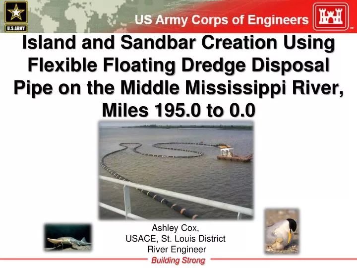
Island and Sandbar Creation Using Flexible Floating Dredge Disposal Pipe on the Middle Mississippi River, Miles 195.0 to 0.0. Ashley Cox, USACE, St. Louis District River Engineer. Brief Background.

E N D
Island and Sandbar Creation Using Flexible Floating Dredge Disposal Pipe on the Middle Mississippi River, Miles 195.0 to 0.0 Ashley Cox, USACE, St. Louis District River Engineer
Brief Background • For years, USACE and partnering agencies have desired to use dredge material to increase overall riverine habitat diversity • MVS acquired rubberized, flexible floating dredge pipe in 2009 for $8M • 67 hoses • 39 ft long • 32” interior diameter • 67” exterior diameter • Closed cell PE foam floating casing • Weight of hose app. 8.5 short tons • 2 – 22.5° elbows • MVS’ Dredge crew developed an assembly method and transportation system for hose • In process of designing/building spill barge
Purpose • Outline engineering considerations for the creation of depositional features using flexible dredge pipe on the Middle Mississippi River
Dredge Disposal Opportunities • Historic Dredging Records • 8 dredging locations were chosen • Average dredge material per year was calculated to determine possible island size depending on material volume • Island size will also depend on island elevation
Depositional Features & Assumptions • Types: • Ephemeral • (Below +20 ft LWRP) • Stable, Non-Vegetated • (+20-25 ft LWRP) • Stable, Vegetated • (+25-30 ft LWRP) Note: Existing Bathymetry of +10 ft LWRP (for islands)
Methods to Stabilize Features 1. No Hydraulic Structure • Goal: Ephemeral bar 2. Hydraulic Structure a. Commonly Used Structures • Goal: Stable Islands • Bull Nose Dikes (Initial) • Dikes (Initial) • Revetment (Final)
b. Innovative Structures • Goal: Stable Island • Design Parameters: • Shape • Location of Structure • Does not negatively impact navigation channel • Placed 250 ft upstream of desired feature location • Location of Depositional Feature • Behind existing structure • Height of Structure • In general, the higher the structure, the higher the stable island • UNET output to determine probability of overtopping at certain elevations
3. Plantings • Goal: Stable Island 4. Combinations • Hydraulic Structures and Plantings • Goal: Stable Island
Island Creation Conclusions • Created islands will be substantially smaller than existing islands • Island footprints will be highly variable and dependent on available material and the existing elevation of the placement site • Based on existing islands, generally: • Vegetated islands - top elevation of >+25 LWRP • Non-vegetated islands - top elevation of +20-25 LWRP • Elevations of <+20 LWRP will be ephemeral • Maintaining a permanent island will require protecting the island • Prior to permanent vegetation, height of island will be constrained by the height of the protective structure • Based on existing data, protective structures should be 250 ft upstream of the proposed island site
Flexible Floating Dredge Disposal Pipe in Action Mississippi River Test Site: River Mile 104.0 Just downstream of Chester, IL November 8, 2011
Dredge Potter Island/Bar created from Dredge Disposal Temporary Spill Barge
Flexible Floating Pipe hook up at Dredge Potter Flexible Floating Pipe looking downstream from pilot house of Dredge Potter
Flexible Floating Pipe with intermittent attached lights Spuds – Used to anchor Spill Barge Flexible Floating Pipe attached to rigid pipe fixed to the Temporary Spill Barge
Helper boat moving the Spill Barge to adjust the disposal location Crane Rigid Discharge Pipe The Temporary Spill Barge
A close view of disposal Material consisted of sand and some gravel
Representatives from Fish and Wildlife Services (FWS), Illinois Department of Natural Resources (IDNR), Missouri Department of Conservation (MDC), and the Corps came out to see the pipe and dredge in action
Surveys of Test Site Dredge Island
Details of Test Site • Initial Island Created November 8, 2011 • 100,000 cubic yards of material • Max Elevation ~ 352 ft (+15 LWRP) • Size ~ 10 Acres • After 2 brief periods of inundation, 4 months later the island had eroded to approximate elevation of 348 ft (+11 LWRP) • After 4 months of inundation, surveys in May, July, & September showed approximate elevation of 342 ft (+5 LWRP)
Questions or Comments? Note: A copy of the paper is available on AREC website - http://www.mvs.usace.army.mil/arec/