GLAS Instrument (Geoscience Laser Altimeter System)
90 likes | 230 Vues
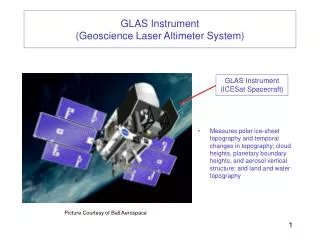
The GLAS (Geoscience Laser Altimeter System) instrument aboard the ICESat spacecraft plays a crucial role in measuring polar ice-sheet topography and monitoring temporal changes. It also evaluates cloud heights, planetary boundary layers, and aerosol vertical structures, as well as land and water topography. Utilizing advanced STOP (Structural-Thermal-Optical) analysis with NASTRAN modeling, the GLAS instrument ensures accurate predictions of optical performance despite thermal distortions. Laser interferometry is employed to measure thermal properties at a microscopic level, enabling precise tracking of deformation and motion.

GLAS Instrument (Geoscience Laser Altimeter System)
E N D
Presentation Transcript
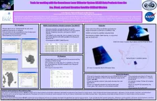
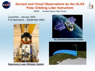
GLAS Instrument(Geoscience Laser Altimeter System) • Measures polar ice-sheet topography and temporal changes in topography; cloud heights, planetary boundary heights, and aerosol vertical structure; and land and water topography GLAS Instrument (ICESat Spacecraft) Picture Courtesy of Ball Aerospace
GLAS Instrument Structure w/ Mass Simulators Telescope Bench 2” Honeycomb Core 0.06” Composite Facesheets Optical Bench 4” Honeycomb Core 0.08” Composite Facesheets
STOP Analysis(Structural-Thermal-OPtical) • Used to predict optical performance of a system degraded by thermal distortions • NASTRAN used to predict motion and deformation of optical components Accurate Material Thermal Properties Required for STOP Analysis GLAS NASTRAN Thermal Model
Laser Interferometer Used to Measure GLAS Bench CTE • Laser Interferometer suitable for real time displacement of components with CTE values as low as 10-9 /K • Temperature can be accurately cycled over wide range • 8” x 8” Samples Information Provided By Precision Measurements and Instruments Corporation (PMIC)
Michelson Laser Interferometer • Helium-neon laser provides stable frequency beam • Laser is split by beam splitter (BS) • First beam is reflected off mirror PZT and passes into vacuum chamber • Second beam passes though BS and enters vacuum chamber • Beams are reflected off sample mounted mirrors and return along their respective paths and interfere, forming a fringe pattern • Beam splitter SP separates finge pattern light and directs them to photo-detectors PD1 and PD2 • Each shift in the fringe pattern corresponds to a change in sample length equal to 1/2 the wavelength of the laser light (12.456 min) Information Provided By Precision Measurements and Instruments Corporation (PMIC)
Composite Face Sheet (Plate Element) CTE = 0.21 min/in*C Aluminum Honeycomb Core (Solid Element) CTE = 0.21 min/in*C (L and W Directions) GLAS Optical Bench NASTRAN Model