Miniature Centrifugal Compressor Testing Solutions for High-Speed Challenges
Solving issues hindering achieving desired speed, focusing on shaft material stress, thermal analysis, and redesigning solutions for efficient miniature compressor testing systems.

Miniature Centrifugal Compressor Testing Solutions for High-Speed Challenges
E N D
Presentation Transcript
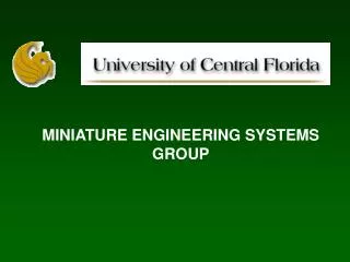
MINIATURE ENGINEERING SYSTEMS GROUP MINIATURE CENTRIFUGAL COMPRESSOR TESTING Presented by Dipjyoti Acharya
Miniature Centrifugal Compressor Testing Problems The compressor could run only upto 98,000 rpm. The factors hindering to achieve our desired speed of 150 K rpm :- 1)The existing Teflon Coupler is not able to transmit power from the motor and causing Bearing Loss as well as failure. 2)Three components namely the Motor Shaft, Compressor Shaft and the Coupler are bringing in Vibrations due to MISALIGNMENT . Solution 1)Eliminate the coupler 2) Compressor and Motor Shafts to be machined to act as male-female joint and acts as a single shaft. 3) Assemble both Motor part and Compressor part by REDESIGNING the whole HOUSING in SINGLE PIECE. 4) Assembled Part to be LASER ALIGNED.
Compressor and Motor Shaft Compressor Shaft Motor Shaft
New Housing Motor Cooling Jacket One Bearing to be eliminated
Miniature Motor Issues • The Shaft ( Titanium Alloy) and Magnet (Samarium Cobalt) • Calculated • Stress due to Centrifugal Force • Thermal Analysis The Magnet and the Shaft have to be assembled at room temperature The shaft SHRINKS more than the magnet. Hence at room temperature the magnet will be loose fit. Thermal Stress analysis were based on assumption that Maximum Stress developed in the shaft will be transmitted to magnet.
Problems with Titanium Shaft Material The GRADES of Titanium Alloy conveniently available in the market have Yield Strength = 1400 MPa Our Calculations show Total Stress = 1553 +388 = 1941 MPa Solution Feedback from motor group Gap can be increased between the magnet and outer diameter of Shaft. REDESIGNING AND ANALYSING with GAP = 1.0 mm
Conclusion Total Stress = 1308.2 MPa 728 MPa (Shaft Centrifugal) + 329MPa (Shaft Thermal) + 251.2 MPa (Magnet Centrifugal) We can find Titanium Grades for our application !! Yield Strength >1400 MPa Thermal Stress 130 MPa < Magnet UTS = 833 MPa (Compressive) Magnet is safe !!
Future Work To look for 1) Available GRADES of Titanium and its suppliers TIMET has Grades with Yield Strength > 1400 MPa 2) Possible ways of machining the section, SOMEC can do the machining 3) Bearings to operate at 200 K rpm. Available with Barden Corporation = DN # = 1.5 million 4) Calculating the Critical Speeds of the whole system