Engineering Systems
Chapter 1. Engineering Systems. Introduction Systems Electrical and Electronic Systems System Inputs and Outputs Physical Quantities and Electrical Signals System Block Diagrams. 1.1. Introduction. Engineering is inherently interdisciplinary

Engineering Systems
E N D
Presentation Transcript
Chapter 1 Engineering Systems • Introduction • Systems • Electrical and Electronic Systems • System Inputs and Outputs • Physical Quantities and Electrical Signals • System Block Diagrams
1.1 Introduction • Engineering is inherently interdisciplinary • Electrical and Electronic Systems represent a major enabling technology • important to all engineers and scientist • A systems approach to engineering • combines: • a systematic/top-down approach • a systemic approach
1.2 Systems • A system can be defined as Any closed volume for which all the inputs and output are known • Examples include: • an engine management system • an automotive system • a transportation system • an ecosystem • Inputs and outputs will reflect the nature of the system
1.3 Electrical and Electronic Systems • Basic functions include elements concerned with the manipulation of electrical energy • Common functions are: • generation • transmission of communication • control or processing • utilisation • storage
System examples • electrical and electronic systems often fall within a range of categories, such as those responsible for: • power generation and distribution • monitoring of some equipment or process • control of some equipment or process • signal processing • communications
1.4 System Inputs and Outputs • Systems may often be described simply by their inputs, their output and the relationship between them
Nature of inputs/outputs will depend on where we draw our system boundaries. For example:
By changing the system boundary we change the nature of the inputs and outputs
Components that interact with the outside world are termed sensors and actuators • in the previous example the microphone represents a sensor • in the previous example the loudspeaker represents an actuator • We will look at sensors and actuators in more detail in later lectures
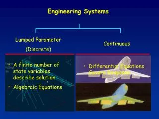
1.5 Physical Quantities & Electrical Signals • The world about us is characterised by a number of physical properties or quantities • e.g. temperature, pressure, humidity, etc. • Physical quantities may be continuous or discrete. • Continuous quantities change smoothly and can take an infinite number of values • Discrete quantities change abruptly from one value to another. • most real-world quantities are continuous • many man-made quantities are discrete
It is often convenient to represent physical quantities by electrical signals. These can also be continuous or discrete • Continuous signals are often described as analogue
Discrete signals are often described as digital signals • Many digital signals take only two values and are referred to as binary signals
1.6 System Block Diagrams • It is often convenient to represent complex arrangements by a simplified block diagram
In an electrical system a flow of energy requires a circuit - a system with a single input and a single output is shown below • this shows the input circuit and the output circuit • the sensor represents the source • the actuator represents the load
We often divide complex circuits into subsystems or modules – as shown below • the output of each module represents a source for the following section • the input of each module represents a load to the previous section
Key Points • Engineering is inherently interdisciplinary • Engineers often adopt a ‘systems approach’ • Systems may be defined by their inputs, their outputs and the relationship between them • Systems interact with the world using sensors and actuators • Physical quantities can be either continuous or discrete • Physical quantities are often represented by signals • Complex systems are often represented by block diagrams