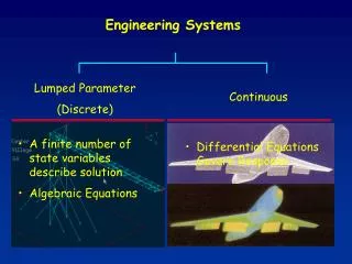
Systems Engineering
Systems Engineering. R. Dekany, A. Bouchez 9/22/10 Integration & Testing Review. Outline. Performance Predictions Requirements Error Budgets Operations Concepts Development Servo Control Work during I&T phase. H . 80. 100. 200. 250.

Systems Engineering
E N D
Presentation Transcript
Systems Engineering R. Dekany, A. Bouchez 9/22/10 Integration & Testing Review
Outline • Performance Predictions • Requirements • Error Budgets • Operations Concepts Development • Servo Control • Work during I&T phase
H 80 100 200 250 Strehl vs. Observing Wavelength(for various levels of RMS wavefront error in nm)
Error Budget Example V = 6.5 NGS Median seeing and wind 30 deg zenith (r0 = 8.4 cm) Includes: 21 nm RMS anisoplanatism (1.0 arcsec) 35 nm RMS margin Total effective WFE = 104 nm RMS1-D TT error = 2.3 mas RMS H-Strehl = 85%
Error Budget Example V = 4.5 NGS Median seeing and wind 10 deg zenith (r0 = 9.1 cm) Includes: 18 nm RMS anisoplanatism (1.0 arcsec) 35 nm RMS margin Total effective WFE = 92 nm RMS1-D TT error = 1.9 mas RMS H-Strehl = 88%
Error Budget Example V = 6.5 NGS Median seeing and wind 60 deg zenith (r0 = 6.1 cm) Includes: 44 nm RMS anisoplanatism (1.0 arcsec) 35 nm RMS margin Total effective WFE = 145 nm RMS1-D TT error = 2.4 mas RMS H-Strehl = 72% Large (and unreliable) contribution from Dispersion Displacement Error
Error Budget Example V = 16.5 NGS Median seeing and wind 20 deg zenith (r0 = 8.9 cm) Includes: 181 nm RMS anisoplanatism (15 arcsec) 35 nm RMS margin Total effective WFE = 465 nm RMS1-D TT error = 33 mas RMS K-Strehl = 17% ~2% sky fraction at b = 30 (Same performance achieved for r0 = 15 cm V = 17.5 NGS located 30 arcsec off-axis ~6% sky fraction at b = 30)
Well-Corrected Subaperture (WCS) Pathfinder Experiment (Serabyn, et al.) • Use of an off-axis subaperture with 8cm projected actuator spacing to validate PALM-3000 performance on bright NGS WCS AO stimulus
WCS experiment confirms PALM-3000 performance predictions SAO 37735 V = 5.1, 6.3 Sep = 0.34” B-band (400-450 nm)Strehl ratio 0.10 – 0.12 /D (B) = 59 mas K-band Strehl ratio 0.92-0.94 RMS WFE 85 -100 nm Strehl stability: ~1% RMS (G. Serabyn)
Requirements • Science requirements • Instrument requirements • Subsystem requirements • Software • Stimulus • HOWFS • Electronics • Optical Bench • Real-time Processor
Error Budgets • Wavefront Error • Transmission & Emissivity • Model of trans./emissivity with degraded coatings eg. after 1 year • Flexure • Allocations to opticalbench, opticsmounts, HWFS • Acquisition Time • Dominated by hardware, drives software automations & GUI design • System Downtime • Allocations to software and hardware failures 13
Operations Concepts • We have developed an Observing Scenarios Document, which covers • Lab procedures (alignment, calibration) • Observing procedures (acquisition, dithering) • Project 1640 survey observing • Effectively provided detailed requirements flowdown from Science to Software • Used as starting point for lab I&T test plans 14
Servo Control Design Flexible control of 2 DMs in a woofer-tweeter arrangement: Direct control of HODM with offload to LODM Modal splitting between DMs Use leaky integrator & regularized reconstructors to control blind modes Calibration WFS updates HOWFS centroid offsets every ~60s
Camera & Servo Modes • Currently operating the testbed in camera mode 0, servo mode 3 • Developing reconstructors for servo modes 0, 1, and 4 16
Systems Engineering tasksin I&T phase • Verify requirements compliance (IRD) • Complete the development of reconstructors for woofer-tweeter control • Develop test plans for system-level performance validation (eg. Plant function measurement) • Revisions of 1999/2003/2005 upgrade test plans
HOWFS Subaperture Alignment In the 63x63 subaperture mode the pupil alignment preserve Fried geometry. In the other modes, we will use use modal control. 63 63 32 32 16 16 8 8