Systems Engineering
Systems Engineering. Michael Ludlam EFW Systems Engineer Space Sciences Lab University of California, Berkeley. System Engineering Outline. Requirements & Verification Design Overview ETU Status Changes since PDR ICDs Environments Resource Budgets PDR RFA’s Peer Reviews

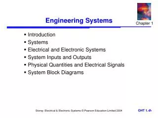
Systems Engineering
E N D
Presentation Transcript
Systems Engineering Michael Ludlam EFW Systems Engineer Space Sciences Lab University of California, Berkeley RBSP EFW ICDR
System EngineeringOutline • Requirements & Verification • Design Overview • ETU Status • Changes since PDR • ICDs • Environments • Resource Budgets • PDR RFA’s • Peer Reviews • Deviations / Waivers • Anomaly Reports • FMEA / Design Principles • Fault Tolerance • Lessons Learned • Configuration Management RBSP EFW ICDR
Requirements • Requirements flowed down to EFW via the Science Team Allocated Requirements Document (STARD) from the Mission Requirements Document (MRD) • Includes references to the EFW Compliance Matrix, Environmental Spec, EME Spec, Contamination Control Spec, ICD, etc. • Includes Instrument Functional and Performance Requirements • An Instrument Requirements Document (RBSP_EFW_SYS_001) flows these requirements down to the EFW subsystems • Requirements linked the STARD requirements • Requirements linked to the subsystem specifications • Subsystem specifications refer to their requirements from the IRD and how the design meets those requirements • Flight and SOC Software Requirements documents flow their requirements from the IRD down to the software modules • IRD specifies how each requirement is to be verified (Test, Analysis, etc) • EFW System Engineer has validated that the subsystem specifications describe an instrument that meets all the STARD requirements. RBSP EFW ICDR
IRD Sample RBSP EFW ICDR
Requirement Changes since IPDR • Changes since PDR: • Parent requirements now flow from STARD not MRD. This has been updated in the EFW requirements document (IRD). • All requirements directly mapped except: new requirement about range safety replacing old safety plan. • Space Weather capabilities added. • Shared data bits to cover AXB shadowing. • Modification to EFW to EMFISIS requirements as performance details firmed up during phase C (from EFW to EMFISIS ICD). • Addition of backup MAG mode. RBSP EFW ICDR
Verification • Instrument Requirements Document (RBSP_EFW_SYS_001) identifies briefly how each requirement is verified. • Verification, Validation, Test, and Calibration Plan (RBSP_EFW_TE_001) describes a plan for how requirements are verified • Discussed in I&T section • Requirements are verified as early as possible at a low level • Verifies subsystems, Retires risk • Requirements are verified at the highest level of assembly possible • Often involves verifying a requirement at several levels • System Engineer tracks Verification against IRD • Reports on status at PER, PSR RBSP EFW ICDR
Key Performance Requirements RBSP EFW ICDR
Key Subsystem Requirements RBSP EFW ICDR
Block Diagram RBSP EFW ICDR
Subsystem Mechanical IDPU AXB (1 of 2), Stowed SPB (1 of 4), Stowed RBSP EFW ICDR
Booms Deployed Axial Boom Deployment Unit (1 of 2) Four 40-50m Spin Plane Booms (SPB) Two 6m Axial Booms (AXB) Spin Plane Boom Deployment Unit (1 of 4) (IDPU Mounted Inside Bus) RBSP EFW ICDR
Instrument Status • ETU Instrument Built • 1 AXB (Functional Tested, Vibrated, TVAC’d) • 1 SPB (Functional Tested, Vibrated, TVAC’d) • Preamps for SPB and AXB (Functional Tested, TVAC’d) • IDPU • BEB ETU Built, Functional Tested, Integrated with IDPU. Second BEB ETU currently undergoing testing. • DFB ETU Built, Functional Tested, Integrated with IDPU. Second DFB ETU currently being fabricated (likely flight layout). • DCB ETU Built, Functional Tested, Integrated with IDPU, used for FSW verification. Flight layout nearly complete. • LVPS ETU Built, Functional Tested, Integrated with IDPU. PCB circuit not tested, currently being assembled. Improvements being made to LVPS with further testing. LVPS layout for second ETU (possibly flight) due in October 09. • Chassis vibrated. • ETU harness built, ready for check on S/C mock up. RBSP EFW ICDR
Instrument Status • EFW to EMFISIS interface test completed at University of Iowa, August 09. • Performance Test of SPB with IDPU completed, August 09. • Performance Test of AXB with IDPU in late September 09. • Power Control Circuit to be tested with Boom Simulators in September 09 • EMC ETU Test, October 09. • Thermal tests of BEB and LVPS, October 09. RBSP EFW ICDR
Major Design Changes since IPDR RBSP EFW ICDR
ICDs • Spacecraft to EFW ICD released and signed off (7417-9083) • No open issues. • EFW to EMFISIS ICD and awaiting to be signed off (7417-9089) • MOC/SOC ICD in rev ‘–’; awaiting first official release (7417-9050) • EFW Subsystem specifications define interfaces between subsystems: • IDPU Backplane specification – RBSP_EFW_BPL_001M • IDPU LVPS specification – RBSP_EFW_LVPS_001J • Axial Boom specification – RBSP_EFW_AXB_001A • Spin Plane Boom specification – RBSP_EFW_SPB_001- • Interconnect Drawings • RBSP_EFW_SYS_008H (harnessing) • RBSP_EFW_SYS_015D (pinouts) • RBSP_EFW_AXB_002Y (AXB wiring schematic) • RBSP_EFW_SPB_002N (SPB wiring schematic) • RBSP_EFW_SYS_006 (Grounding) • RBSP_EFW_SYS_007A (IDPU Grounding) RBSP EFW ICDR
Flight Software • Flight Software Development Plan documented in RBSP_EFW_FSW_001 • Flight Software Requirements documented in RBSP_EFW_FSW_002 • Major Requirements Include: • Spacecraft Interface Handling • Command Reception & Distribution • Real-Time Data Collection and Playback • On-Board Evaluation for Burst Triggering • Burst Data Collection and Playback • Boom Deployment Control • Details of flight software requirements and design discussed later RBSP EFW ICDR
SOC Software • SOC Software Development Plan documented in RBSP_EFW_SW_001 • SOC Software Requirements documented in RBSP_EFW_SYS_010 • Major Requirements Include: • Command and Telemetry GSE (CTG): • Real time telemetry ingestion from MOC • Real time telemetry display, trending, and limit monitoring • Automated operator call-up on limit violation • Command Encoding and forwarding to MOC • Science Data Center (SDC): • Near-real time science displays • Off-line processing including Level 0 to Level 1,2 processing • Burst selection • Science Data Analysis • Details of SOC software requirements and design discussed in GSE and SOC sections, and will be reviewed at the EFW SOC CDR (Jan 2010). RBSP EFW ICDR
Environmental • EFW to survive all environments to be encountered during ground operations, launch, and on orbit • EFW to operate in spec over all environments to be encountered during ground functional tests, on-orbit commissioning and science phases • Science Performance not achieved until booms deployed (during commissioning) • RBSP Environmental Requirements called out in ERTRD (7417-9019) • RBSP EME Requirements called out in EMECP (7417-9018) • EFW Verification Plan described in RBSP_EFW_TE_001 • Describes how EFW will verify compliance with requirements, including environmental requirements • Plan discussed in more detail in I&T section RBSP EFW ICDR
Environmental Test Matrix RBSP EFW ICDR
Environmental Test Matrix RBSP EFW ICDR
Environmental Test Matrix RBSP EFW ICDR
Mechanical • Instrument designed to ERTRD: • Limit Loads, Stiffness, Venting, Shock • Mechanical Interfaces, Mass NTE called out in the ICD (7417-9083) • Instrument tested per Environmental Spec: • Mass Properties at component level • Mass, CG • MOI by analysis • Sine, Random vibration at component level • ETU to qualification levels • IDPU and SPB FM to qualification levels, AXB FM to acceptance levels. • No acoustic test planned (no acoustically sensitive parts) • One single item does not follow ‘test as you fly’ approach – AXB deployment after vibration. Boom then re-stowed and Thermal Vacuum started. Thermal Vacuum deployments are separate for whip and stacer. • Mechanical Design and Analyses called out in Mechanical section RBSP EFW ICDR
Thermal • EFW interface temperature limits called out in the MRD and ICD • EFW components conductively coupled to spacecraft deck • EFW Thermal design verified by analysis and Thermal Vacuum testing • Analysis to include launch transients (heating) • Modeling and Analysis performed cooperatively between EFW and APL • Verification testing (Thermal Vac) described in I&T section • Thermal design and analysis described in the Thermal Design presentation. RBSP EFW ICDR
EME (1) • Instrument conforms to EMECP in 7471-9019: • Magnetics • Identified magnetic materials and circuits are provided to Magnetics Working Group, which shall maintain a watch list and participate in analysis and suggestions for mitigations as required • Deployment motors contain permanent magnets, and will be shielded • THEMIS test results indicate shielding is effective • Magnetics will be verified by magnetics screening at the component level (ETU and Flight) • Test to be performed by EMFISIS MAG personnel after CDR on ETU. • ESC • Exterior surfaces are conductive and connected to chassis ground • Boom exterior connected via a resistor • ESC Verification at the component level • Verifed and documented for both SPB and AXB. • Radiation • IDPU and preamp shielding to mitigate radiation environment • Parts selected for radiation tolerance as demonstrated by TID, SEE tests, verified by APL PCB (see Radiation Slide later) RBSP EFW ICDR
EME (2) • DDD • IDPU shielding to 350 mils, including connectors • Preamps have survived DDD testing (ambient and cold) • Spacecraft data interface uses APL-demonstrated DDD-insensitive parts • EFW boom unit interface DDD immunity by analysis (mostly capacitive protection) • EMFISIS interface DDD immunity by analysis and test. • EMC: • IDPU box design includes EMC closeout (stair-step joints, vent shielding, connector close-out) • Harness has complete over-shield braid terminated on connector backshells • Supply frequency is at 199.75kHz (IDPU, BEB) and 399.5kHz (Floaters), synchronized to IDPU clock. • Supply has front end filtering, soft start • Verification by EMC tests: • ETU (CE) • FM1 (CE, CS, RE, RS, BI, On/Off transients) • FM2 (CE, BI) • Will partially deploy SPB to support Observatory EMC self-compatibility test RBSP EFW ICDR
Radiation • Instrument designed to mission curve. Preamps to 100kRad, IDPU to 33kRad. • Radiation testing since PDR: • Mechanical Samples • Sample of Aluminum with Electroless Nickel Plating with Teflon Impregnate. Passed. • AXB harness with Tefzel overwrap Passed. • Hemisphere coated with DAG-213. Passed. • TID • Max256 Passed. • OP15 Passed. • HA5127 Passed. • AD822 Passed. • SEL • AD5544 Passed. • MAX256 Passed. • Waivers • SEL on LTC1604 and DCB Flash Memory Approved. RBSP EFW ICDR
Grounding Diagram RBSP EFW ICDR
System EngineeringMass Budget • Mass has grown 3.07kg (14%) since IPDR. 2kg is from longer harness / extra connections on bulkhead. 0.7kg from AXB due to longer stacer (14m tip to tip) and extra stacers coils held undeployed. RBSP EFW ICDR
Power Budget • Increase of 1.4W since IPDR • This is mostly due to inefficiency in the LVPS. Currently working to increase this. • BEB increase is due to running the HV at 225V. • FPGA current on flight units is uncertain at this time – no experience with RTAX parts, relying on power calculators. • 3 Power Services: • Operating Power (10.33W CBE, 1.05A Peak) • Spin Plane Boom Deployment Power (2A peak power, worst case) • Axial Boom Power (2.25A peak power worst case) RBSP EFW ICDR
Telemetry Budget • Proportions of real time data and playback of burst are adjustable to keep within 12kbps budget. RBSP EFW ICDR
Commanding • Real Time Instrument Command Requirements: • Configuring instrument at power-on (~50 commands) • Boom Deployment (up to 10 commands/minute during deployment) • Adjusting instrument periodically (~20 commands/month) • Burst Request (up to ~20 commands/day) • Rare Memory Load (<64kbytes) • Time-Tagged Command Requirements • Mode adjustments at different parts of the orbit (~20 commands/orbit) • Most commands are small (~10 bytes with header) • Except Memory Load commands RBSP EFW ICDR
Limited Life • EFW does not have any limited life items by the definition used, however a number of items will be tracked for the purposes of best practice. RBSP EFW ICDR
PDR RFA’s • 25 RFA’s raised for EFW to answer at PDR • 18 Have been closed. • 2 Response submitted and awaiting closure (SPB Structural Design Margins, IDPU Board Thermal) • 5 Remain open (related to SOC (to be closed by time of EFW SOC CDR – Jan 2010)). RBSP EFW ICDR
Peer Reviews • Three informal Peer Reviews have been held: RBSP EFW ICDR
Deviations & Waivers EFW has 18 waivers / deviations. 5 withdrawn, 1 recently submitted, all others approved. RBSP EFW ICDR
Anomaly Reports • Anomaly Reports were used to track failures on ETU (less formal than flight PFR but allows EFW to track issues that affect the design or setup). • 5 AR’s raised during ETU development. 4 closed. 1 awaiting further testing. • Problem Failure Report process used on flight units at level of an assembly and up. RBSP EFW ICDR
FMEA & Design Principles • Project (APL) has performed FMEA analysis on: • EFW / Spacecraft Interface • EFW / EMFISIS Interface • EFW is due to provide FMEA analysis on: • EFW / GSE Interfaces. • No special reliability concerns in design. • Approach to ‘worse case’ design: • Where simple, redundancy is implemented. • e.g. frangibolt switches on AXB. • Where more complicated, failure modes are analyzed and if appropriate steps taken to mitigate them. • Power switch on Flash memory. • Design margin for mechanical components is as per NASA 5001. • Electrical components derated as per INST-002 and stress analysis performed. • Thermal analysis and tests run to verify components are not used outside of operating regime. • Heritage designs used where possible. RBSP EFW ICDR
Lessons Learned • EFW instrument is based on long heritage of similar instruments flown on CRRES, Polar, Cluster-II, FAST and most recently THEMIS (30+ years of development). Examples of lessons learned are: • Simplified sensor design (Cluster) • Early integration with EMFISIS (Polar) • BEB HV running at 225V (CRRES) • Frangibolt firing times are well known but addition of power cut off switch prevents overheating (THEMIS) • DFB configurations are managed through FSW, rather than having to configure both the DFB and FSW separately (THEMIS) • Power converter frequency of floating supplies is above measurement range (THEMIS) • MGSE (tool) to aid removal of IDPU boards from chassis (THEMIS) RBSP EFW ICDR
Configuration Management • EFW Configuration Management Plan RBSP_EFW_PA_010 • Details how documentation and flight hardware is controlled at UCB. • More information on how procedures are controlled in the I&T presentation. • Specifications and Requirements are controlled by the Systems Engineer. • Documents are stored on SSL ftp site, where only the SE posts revisions and updates. • Drawings are controlled by engineers until released for flight. Once released the process for updating the drawings follows the configuration management plan. • Mechanical Drawings to be released: 368 • Electrical Drawings to be released: 8 RBSP EFW ICDR
Backup Slides • PDR RFA AI • Peer Review AI RBSP EFW ICDR
Closed PDR AI’s (1) RBSP EFW ICDR
Closed PDR AI’s (2) RBSP EFW ICDR
Mechanical Peer Review AI (1) • Steve Vernon • Cat 1) • AXB mounting to two decks raises red flag. Have additional discussions with APL to make sure all have sufficient insight into issues. Seems satisfied with analysis. • Continued discussions with APL have finalized the mounting and responsibilities. Both sides are convinced that sufficient leeway exists for the mounting. • SPB Need to ensure that installation with harness is vetted with APL harness team • “concern #2”: This is not very clear, but seems to concern our lack of deployment testing at the SC level, though he also mentions vibration/dynamic levels. Bottom line is he thinks we’ve got a reasonable plan. • Apply epoxy to Kevlar braid knots. • Epoxy will be applied to the knot after it is tied. • Cat 2) • Clearly document deviations from test-as-you-fly approach. • Mike Sholl • Cat 1) • Log motor current during TV deployments on every unit. Include in EIDP. • SPB: Ensure there have been no motor drive electronics chsnges (reverse bias MOSFET?) • SPB: Add provisions for GSE to hold SPBs during SC installation. • AXB flexure – check for yielding in all three axes? Also thermal? • FEA of the Flexure shows the unit will withstand all loading cases with a minimum margin of 1. • AXB – flexure min fillet radius called out? • Yes. • AXB – slide 15 , anything electrically isolated after bolt break? • No. • AXB -- No shear pin • Correct. • AXB -- Lubricate Al/SS sliding joints, change mat’ls if possible • All hinge pins will be lubricated with Braycote 601EF during assembly. • AXB -- Flexure – check nonlinearities • Sufficient margins exist to accommodate non-linearities. Load testing of the unit will verify yielding does not occur in flight loading cases (x1.25). • Thermal -- IDPU black kapton – what happens if pulls loose? RBSP EFW ICDR
Mechanical Peer Review AI (2) • Why no list of Theta jc? • IDPU thermal mass need extended test duration? • IDPU -- Feet look weak • Drumheading of boards & shields • Kapton tape or use G10 for shields • Inductors not supported on LVPS • Cat 2) • SPB -- List missions in Heritage section. • SPB -- Put baseline design before heritage. • SPB – slide 4, explain 4.7cm resolution. • List limit loads and design guidelines up front. • SPB -- Add thermal design detail – who, surfaces, heaters, etc. • SPB -- Slide 10: says it’s a TiNi pinpuller (?) • SPB Add # planned deployments vs. TiNi allowable • Actuator force margins? • What happens at EOT if motor keeps running • See RFA#26 from IPDR. • AXB: need failure modes assumptions • See RFA#26 from IPDR. • AXB: slide 11, add oversize in holes. • Done. • Bobby Besuner • Cat 1) • AXB -- Make sure linear elastic analysis is appropriate for drumhead flexure deflection and stress analysis. • Done. • Look at how big of a step there is between adjacent wraps of the outermost ply of the tube and consider how that might affect bond thickness and fit of the outer aluminum fittings. • All fittings fit tubes. Total thickness variation is <0.003”. • Cat 2) • SPB – open with better overview of system. List requirements and definitions. • Summarize somewhere the various cable tensions that cause end-of-wire, shear-pin breakage, metering wheel slippage, etc. • Include a description of the margins on the pin-puller along with a discussion of number of cycles expected/allowed. • Consider an alternate accelerometer location rather than the door. RBSP EFW ICDR
Electrical Peer Review AI’s RBSP EFW ICDR
EFW – DFB Peer Review Action Item Summary (1of2) RBSP EFW ICDR 46
EFW – DFB Peer Review Action Item Summary (2of2) RBSP EFW ICDR 47