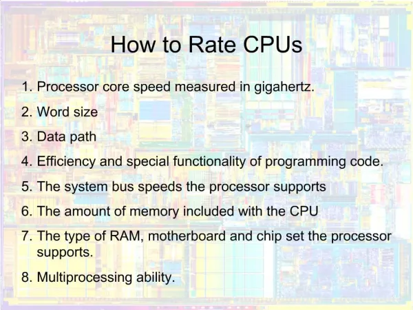
CPUs
CPUs. Input and output Supervisor mode, exceptions, traps Co-processors. I/O devices. Usually includes some non-digital component Typical digital interface to CPU:. status reg. CPU. mechanism. data reg. Application: 8251 UART.

CPUs
E N D
Presentation Transcript
CPUs Input and output Supervisor mode, exceptions, traps Co-processors
I/O devices • Usually includes some non-digital component • Typical digital interface to CPU: status reg CPU mechanism data reg
Application: 8251 UART • Universal asynchronous receiver transmitter (UART) : provides serial communication • 8251 functions are integrated into standard PC interface chip • Allows many communication parameters to be programmed
Serial communication • Characters are transmitted separately: no char bit 0 bit 1 bit n-1 ... stop start time
Serial communication parameters • Baud (bit) rate • Number of bits per character • Parity/no parity • Even/odd parity • Length of stop bit (1, 1.5, 2 bits)
8251 CPU interface 8251 status (8 bit) CPU xmit/ rcv data (8 bit) serial port
How to communicate with the registers in the interface • Memory-Mapped I/O • Isolated I/O • Advantages and disadvantages
Programming I/O • Two types of instructions can support I/O • special-purpose I/O instructions • memory-mapped load/store instructions • Intel x86 provides in, out instructions Most other CPUs use memory-mapped I/O • I/O instructions do not preclude memory-mapped I/O
ARM memory-mapped I/O • Define location for device: DEV1 EQU 0x1000 • Read/write code: LDR r1,#DEV1 ; set up device adrs LDR r0,[r1] ; read DEV1 LDR r0,#8 ; set up value to write STR r0,[r1] ; write value to device
Peek and poke • Traditional HLL interfaces: int peek(char *location) { return *location; } void poke(char *location, char newval) { (*location) = newval; }
Modes of Transfer • Data transfer under program control • Busy-waiting, Polling • Interrupt • DMA transfer
Busy/wait output • Simplest way to program device • Use instructions to test when device is ready current_char = mystring; while (*current_char != ‘\0’) { poke(OUT_CHAR,*current_char); while (peek(OUT_STATUS) != 0); current_char++; }
Interrupt I/O • Busy/wait is very inefficient (Why?) • CPU can’t do other work while testing device • Hard to do simultaneous I/O • Interrupts allow a device to change the flow of control in the CPU • Causes subroutine call to handle device
Interrupt interface intr request status reg CPU intr ack mechanism IR PC data/address data reg
Interrupt behavior • Based on subroutine call mechanism • Interrupt forces next instruction to be a subroutine call to a predetermined location • Return address is saved to resume executing foreground program
Interrupt physical interface • CPU and device are connected by CPU bus • CPU and device handshake • device asserts interrupt request • CPU asserts interrupt acknowledge when it can handle the interrupt
Example: character I/O handlers void input_handler() { achar = peek(IN_DATA);/*get char*/ gotchar = TRUE; poke(IN_STATUS,0);/* reset status*/ } void output_handler() { }
Example: interrupt-driven main program main() { while (TRUE) { if (gotchar) { poke(OUT_DATA,achar);/*put char*/ poke(OUT_STATUS,1);/*set status*/ gotchar = FALSE; } } }
a head head tail tail Example: interrupt I/O with buffers • Queue for characters:
Buffer-based input handler void input_handler() { char achar; if (full_buffer()) error = 1; else { achar = peek(IN_DATA); add_char(achar); } poke(IN_STATUS,0); if (nchars == 1) { poke(OUT_DATA,remove_char(); poke(OUT_STATUS,1); } }
Debugging interrupt code • What if you forget to save and restore registers? • Foreground program can exhibit mysterious bugs. • Bugs will be hard to repeat---depend on interrupt timing.
Priorities and vectors • Two mechanisms allow us to make interrupts more specific: • Priorities determine what interrupt gets CPU first • Vectors determine what code is called for each type of interrupt • Mechanisms are orthogonal: most CPUs provide both
Prioritized interrupts device 1 device 2 device n interrupt acknowledge CPU L1 L2 .. Ln
Daisy chain interrupt acknowledge device 1 device 2 device n int vector (Id) CPU INTR
Interrupt prioritization • Masking: interrupt with priority lower than current priority is not recognized until pending interrupt is complete • Non-maskable interrupt (NMI): highest-priority, never masked • Often used for power-down
Example: Prioritized I/O :interrupts :foreground :A :B :C B C A A,B
Interrupt vectors • Allow different devices to be handled by different code • Interrupt vector table: Interrupt vector table head handler 0 handler 1 handler 2 handler 3
Interrupt vector acquisition :CPU :device int req receive request int ack receive ack receive vector int vector
continue execution intr? N Y N ignore Y ack Y Y N bus error timeout? vector? Y call table[vector] Generic interrupt mechanism Assume priority selection is handled before this point. intr priority > current priority? Int enabled?
Interrupt sequence • CPU acknowledges request • Device sends vector • CPU calls handler • Software processes request • CPU restores state to foreground program
Sources of interrupt overhead • Handler execution time • Interrupt mechanism overhead • Register save/restore • Pipeline-related penalties • Cache-related penalties
ARM interrupts • ARM7 supports two types of interrupts: • Fast interrupt requests (FIQs) • Interrupt requests (IRQs) • Exception table starts at location 0
ARM interrupt procedure • CPU actions: • Save PC. Copy CPSR to SPSR • Force bits in CPSR to record interrupt • Force PC to vector • Handler responsibilities: • Restore proper PC • Restore CPSR from SPSR • Clear interrupt disable flags
6 7 M 0 M 1 M 3 M 2 M 4 T F I N Z C V Q Interrupt request exception • IRQ is generated externally by asserting the IRQ input on the processor • Lower priority than FIQ • I bit : disable IRQ when it is set • F bit: disable FIQ when it is set
IRQ R14_irq = address of next instruction to be executed + 4 SPSR_irq = CPSR CPSR[4:0] = 0b10010 /* enter IRQ mode */ CPSR[5] = 0 /* execute in ARM state */ /*CPSR[6] is unchanged */ CPSR[7] = 1 /* disable normal interrupt */ If high vectors configured then PC = 0xFFFF0018 else PC = 0x00000018 To return SUBS PC, R14, #4 /* PC from R14_irq, CPSR from SPSR_irq */
FIQ R14_fiq= address of next instruction to be executed + 4 SPSR_fiq = CPSR CPSR[4:0] = 0b10001 /* enter FIQ mode */ CPSR[5] = 0 /* execute in ARM state */ CPSR[6] = 1 /* disable fast interrupt */ CPSR[7] = 1 /* disable normal interrupt */ If high vectors configured then PC = 0xFFFF001C else PC = 0x0000001C To return SUBS PC, R14, #4 /* PC from R14_fiq, CPSR from SPSR_fiq*/ * The FIQ handler can be placed directly at address 0x0000001C or 0xFFFF001C, without requiring a branch instruction from the vector.
ARM interrupt latency • Worst-case latency to respond to interrupt is 27 cycles: • Two cycles to synchronize external request • Up to 20 cycles to complete current instruction • Three cycles for data abort • Two cycles to enter interrupt handling state
CPUs MPC 850 interrupt Supervisor mode, exceptions, traps Co-processors
Exceptions back
Exceptions (cont’d) back
Exception Handling • Vector Table Starting Address • Registers: SRR0, SRR1 • SRR0: return address • SRR1: Machine State (from MSR)
Programming the SIU interrupt controller • SIU interrupt pending register: SIPEND • SIU interrupt mask register: SIMASK • SIU interrupt edge/level register: SIEL • SIU interrupt vector register: SIVEC
Internal Memory Map Register (IMMR) • ISB : internal space base; all16 bits can be programmed • MPC 850 memory resource: a contiguous blocks of 16 KB • Can be mapped on 64-KB resolution through IMMR • IMMR: MPC850-specific SPR #638