Statistical Process Control Implementation in Semiconductor Manufacturing
Statistical Process Control Implementation in Semiconductor Manufacturing . Tzu-Cheng Lin 林資程 Advanced Control Program/ IIPD/ R&D Taiwan Semiconductor Manufacturing Company, Ltd tclinr@tsmc.com, edward.ece97g@nctu.edu.tw. March 26, 2010. Agenda:.

Statistical Process Control Implementation in Semiconductor Manufacturing
E N D
Presentation Transcript
Statistical Process Control Implementation in Semiconductor Manufacturing Tzu-Cheng Lin 林資程Advanced Control Program/ IIPD/ R&DTaiwan Semiconductor Manufacturing Company, Ltd tclinr@tsmc.com, edward.ece97g@nctu.edu.tw March 26, 2010 Page 1 of 56
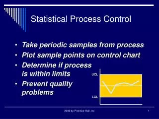
Agenda: 1. MVA application:Advanced Bi-Variate Semiconductor Process Control Chart. 2. MVA application:Yield2Equipment Events Mining. 3. PLS application:Virtual Metrology of Deep Trench Chain. 4. Time series application:KSI-Based to Predict Tool Maintenance. 5.Survival application:Advanced Queue-Time to Yield Monitoring System. 6.SPC chart application:Smart Process Capability Trend Monitoring System. This presentation will cover the following topics: Leadership in Analytics Page 2 of 56
Case(1): MVA applicationAdvanced Bi-Variate Semiconductor Process Control Chart. Page 3 of 56
Process Variation = (Process Metrology Value) + (Tool Healthy Quality) + (Metrology Tool Calibration) SPC monitoring system FDC monitoring system MSA calibration scheme Innovative idea !! SPC FDC Advanced Bi-Variate Semiconductor Process Control Chart Motivation: As you know, In Line Process Control is a great important task on semiconductor manufacturing. We usually use the SPC system to monitor the process measurement data, and use the FDC system to monitor the tool healthy index. Although engineers via theses two regular systems, they could check the process is stable or not ?? BUT it is time consuming for engineers, …….. If we could build up the Bi-Variate Process Control Chart which based on the relationships between In-Line metrology data and FDC tool parameter monitoring data, and provide the Ellipse Control Region to real time tell engineers what’s current status for the latest process capability is stable or not?? In this way, it will give a big hand for engineers not only to monitor the SPC chart, but also to monitor the FDC chart at the same time. Page 4 of 56
Advanced Bi-Variate Semiconductor Process Control Chart (1) Process_A (3) (6) (5) (4) (7) (X,Y) FDC Summary Value (Y) (9) 9 (8) (10) 8 (2) In-Line Metrology Value (X) Innovative idea profile: Remarks: (1) The box is showing the process information on this chart. (2) X-axis is the In-Line metrology value (X). (3) Y-axis is the FDC summary value (Y). (4) The light-gray area is the Ellipse Control Region with 1 sigma. (5) The mid-gray area is the Ellipse Control Region with 2 sigma. (6) The dark-gray area is the Ellipse Control Region with 3 sigma. (7) The red point is contributed from (X,Y) and draw it on this specific control chart. (8) When the point is out of 3 sigma area, it’ll give a ‘x’ symbol to represent the OOC case. (9) When the point is OOC, it’ll also provide the Wafer_ID nearby it. (10) The ‘green’, ‘yellow’, and ’red’ light will point out the degree of stability on this process. Page 5 of 56
Full-Line Bi-Variate Semiconductor Process Control Chart It can integrate semiconductor full-line process & tool information into one system, and to be a kind of real time control tool for modern 12” iFab. Via this advanced process control chart, we’d be more easily to check the process status. Page 6 of 56
LCL Target UCL Case study ALD NOLA Depth is a new process for new generation. So, we’re going to use this “Advanced Bi-Variate Semiconductor Process Control Chart” to monitor this critical process: 1) In-line metrology value: Depth (nm). 2) Equipment FDC parameters: Var1-Var25. 3) 34 raw data sets. Trial data looks like… ALDA102-PM4 Page 7 of 56
Step(1): Select Key Steps and Parameters Due to for ALDA equipment has so many tool parameters, we need the engineers/ vendors to provide the key process steps (some critical steps in the recipe) and parameters where measurements have significant effect on product quality. Process step Identify the key steps and variables. Variables :the key parameter in corresponding step. Page 8 of 56
Matrix [34X25] ….. *Huge data reduce to only ONE index: *FDC Summary Value: Step(2): T-Score Transformation TOOL: ALDA102/PM4 ChamberPressure PumpingPressure MFC1 GasLineHeater1Temp StageHeaterInTemp StageHeaterOutTemp Source1HeaterTemp Source2HeaterTemp ThrottleValveHeaterTemp PumpingLineHeaterTemp ChamberWallHeaterTemp ChamberBottomHeaterTemp SHInletHeaterTemp VATValveHeaterTemp Source1_Outlet_Pressure ………. ……… ….. … .. . Based on each wafer, we’d provide the one index- FDC summary value, which could represents all tool parameters healthy status. Page 9 of 56
Step(3): Ellipse Control Region • Ellipse Equations: • An ellipse centered at the point (h,k) and having its major axis parallel to the x-axis may be specified by the equation • This ellipse can be expressed parametrically as • where t may be restricted to the interval So, we based on the historical raw data (w/ good wafers), to set up the Ellipse control region, and use the Confident-Interval concept to calculate the 1 to 3 sigma alarm region to be the SPC-like, Bi-Variate process control chart. Page 10 of 56
Step(4): Simulation for NOLA Depth process These four points are in warning control region. (4) (3) The 1 to 3 sigma Ellipse control region. (2) These two points are OOC!! (1) Bi-Variate Semiconductor Process Control Chart: SPC+FDC information. Page 11 of 56
Conclusions • From the simulation testing, it seems that our innovative proposal Advanced Bi-Variate Semiconductor Process Control Chart can monitor the semiconductor process variation successfully. • Advanced Bi-Variate Semiconductor Process Control Chart approach not only can be used to monitor the Process Information (SPC Chart), but also to monitor the Tool Information (FDC Chart)at the same time. • The degree of process capability (like Traffic Lights) for specific critical process also can be known via this novel Bi-Variate process control chart. In this way, the engineers could control process more easily and efficiently. Page 12 of 56
Case(2): MVA applicationYield2Equipment Events Mining. Page 13 of 56
Tool-A PM PM ‧ ‧ ‧ ‧ ‧ ‧ ‧ ‧ ‧ ‧ ‧ ‧ ‧ ‧ ‧ ‧ ‧ ‧ ‧ ‧ ‧ ‧ ‧ ‧ ‧ ‧ ‧ ‧ ‧ ‧ ‧ ‧ ‧ ‧ ‧ ‧ ‧ ‧ ‧ ‧ ‧ ‧ ‧ ‧ ‧ ‧ ‧ T-Score Trend Up YB Yield Trend Down time/date Yield2Equipment Events Mining Novel Idea: MVA T-Score T-Score is an index to represent all tool parameters status. If the T-Score is larger than specific limit we can say that this data point is significant different from the normal condition. During this PM cycle, the Yield and T-Score have high correlation and T-Score is bigger than normal condition. In this way, we can induce that this may occur some critical issues in this specific time period. Another way to point out the abnormal tool !! Page 14 of 56
Invention Program Flowchart • Key Step: certain time period • Variable: critical recipe/ process parameters Variable & Key Step selection • MVA Principal Component Analysis • MVA T-Score calculation • MSPC Hotelling T2 control limit set up [0, UCL] Data transformation to T-Score • Yield & T-score trend up/down monitoring • Pearson Correlation Analysis • Highlight the HIGH correlation PM Cycle to • conductYield2Equipment Events Mining Correlation analysis between Yield & Tool Events Root Cause Analysis • Identify suspected ill-parameters Page 15 of 56
Step(1): Select Key Steps and Parameters Due to for each equipment has so many tool parameters, we need the engineers/ vendors to provide the key process steps (some critical steps in the recipe) and parameters where measurements have significant effect on product quality. Process step Identify the key steps and variables. Variables :the key parameter in corresponding step. Page 16 of 56
Step(2): T-Score Transformation TOOL: ALDA102 / PM5 ChamberPressure PumpingPressure MFC1 GasLineHeater1Temp StageHeaterInTemp StageHeaterOutTemp Source1HeaterTemp Source2HeaterTemp ThrottleValveHeaterTemp PumpingLineHeaterTemp ChamberWallHeaterTemp ChamberBottomHeaterTemp SHInletHeaterTemp VATValveHeaterTemp Source1_Outlet_Pressure ………. ……… ….. … .. . *Huge data reduce to ONLY one index *T2 Score Page 17 of 56
Tool-A ‧ PM ‧ ‧ ‧ ‧ ‧ ‧ ‧ ‧ ‧ ‧ ‧ ‧ ‧ ‧ ‧ ‧ ‧ ‧ ‧ ‧ ‧ ‧ ‧ ‧ ‧ ‧ ‧ ‧ ‧ ‧ ‧ ‧ ‧ ‧ ‧ ‧ ‧ ‧ ‧ ‧ ‧ ‧ ‧ ‧ ‧ ‧ ‧ ‧ ‧ T-Score YB Yield time/date Step(3): Correlation Analysis In this step, we’ll conduct the Pearson’s linear correlation analysis to find out the most important PM Cyclein this process and it will be our Highlight issues. Pearson linear correlation analysis equation Correlation Analysis Table It has high significant correlation !! And then we can put more emphasized eyes on this PM Cycle!! Page 18 of 56
Step(4): RCA-Root Causes Analysis T1 Chart Root Cause Analysis via Multi-Variate Analysis PCA Index Raw Data Highlight the suspected issued parameter based on MVA Index!! Page 19 of 56
Conclusions • From the simulation results, it seems that our proposal Yield2Equip Events Mining modulecan monitor PM Events on Yield effects obviously. • The Yield2Equip Events Mining approach not only can be used to monitorPM performance, but also it is useful to do RCA tasks when the T-Score and Yield have HIGH correlation relationship. Page 20 of 56
Case(3): PLS applicationVirtual Metrology of Deep Trench Chain. Page 21 of 56
predicted DT ETCH CD DT Litho CD DT PHMO CD DT MO CD Virtual metrology of deep trench chain 1.5 days • DT Chain Process Flow: As you know, the deep trench control is more critical for process engineers. Due to the process time between DTMO Etch to DT Etch is about 1.5 days, during this time period no one can be aware of the quality of DT final CD. If we could set up the virtual metrology model according to DT Litho CD, DT PHMO CD, and DTMO CD to predict DT final CD. It will be more helpful to assist in on-line process control. Innovative idea !! Page 22 of 56
Methodology introduced-PLS modeling overview Page 23 of 56
Methodology introduced-PLS modeling geometric interpretation Page 24 of 56
Simulation(1)-Predicted DT final CD via PLS/LSE Tool: D90 OXEC103-chamber A Formula: *From the chart, it seems that we could get the better DTME predicted CD via PLS modeling technical. Page 25 of 56
Simulation(2)-SPC for virtual metrology of DT final CD Tool: T90 OXEC107-chamber A It can correctly catch the process alarm message !! Summary: 1) PLS model predicts the virtual metrology values by the pre-process metrology data. 2) At the same time, SPC scheme will monitor the prediction value of metrology parameter. 3) It will also give alarms to engineers when the prediction value is out of the specification. → So, via this virtual scheme, we could ensure that the process is within specification. Page 26 of 56
Conclusions • Virtual Metrology of deep trench chain. • DT Chain Healthy Index set up. • Early alarm/detection system. • Process grouping for following process. • Improve throughputs for critical process. • Improve line stability. Page 27 of 56
Appendix Page 28 of 56
page.1 Partial least squares regression (PLSR) • Abstract:When the number of X is large compared to the number of observations, the multiple linear regression is no longer feasible ( because of multicolinearity). In order to solve the problem, several approaches have been developed. One is principal component regression (PCR) and the other is Partial least squares regression (PLSR) • Goal: • To solve multicolinearity problem • To reduce data dimension • To predict Y from X and to describe their common structure • To get important X variables • Difference between PLSR and PCR: PLSR finds components from X that are also relevant for Y Page 29 of 56
page.2 Basic concept t = Xw Cov(t) = Cov(Xw) = wTCov(X)w = l1 u = Yc Cov(u) = Cov(Yc) = cTCov(X)c = l2 To find two sets of weights w and c in order to create (respectively) a linear combination of the columns of X and Y such that their covariance is maximum!! Page 30 of 56
page.3 Nonlinear Iterative Partial Least Squares Algorithm (NIPALS) T is score matrix The columns of T are the latent vectors P is loading matrix j=0, E0=Xn×m , F0=Yn×p , uj=any column of Y matrix, t = Xw, u = Yc Page 31 of 56
Case(4): Time series applicationKSI-Based to Predict Tool Maintenance. Page 32 of 56
KSI-Based to Predict Tool Maintenance Due to the tool maintenance schedule is usually arranged by date, wafer run counts, RF hours, and for the furnace process it will also consider the equipment sidewall film thickness, but all of them are not sensitive to catch tool real status which need to conduct PM or not?. However, we all know that correct trend monitoring via tool signals can be used to determine approaching timing for preventive maintenance. In this way, our innovative idea can be described as following: Idea of invention: Once this KSI is greater than a pre-scribed limit (threshold). PM PM Threshold KSI Call for engineers &Call for tool maintenance !! Time KSI: Key Sensitive Index. Page 33 of 56
Invention Program Flowchart • Key Step: certain time period • Variable: critical recipe/ process parameters Variable & Key Step selection • Correlation: the quantity of variables • Screen out key parameter & key step • Extract out the signal characteristics Correlation analysis • Time series models fit the trend of variables • Auto-correlation: the q of MA model • Partial Auto-correlation: the p of AR model • Defined Time Series ARIMA(p,d,q) model • KSI would decide when to call tool maintenance Time series model Page 34 of 56
Step(1): Select key steps and parameters Due to for each equipment has so many tool parameters, we need the engineers/ vendors to provide the key process steps (some critical steps in the recipe) and parameters which measurements have significant effects on product quality. Process step Identify the key steps and variables. Variables :the key parameter in corresponding step. Page 35 of 56
Tool signals Step(2): Extract out KSV from tool signals The KSV (Key Sensitive Process Variables), may not be the measurements itself in corresponding key step. However, we can transform the original tool signals into some statistic quantity, such as slop, area, maxima and minima…,etc., which can really represent the characteristics of tool status. How to extract out the useful tool signal information ?? 1. Time Length 2. Mean 3. Stdev 4. Median 5. Max 6. Min 7. Area 8. Quantile………………. Page 36 of 56
Pearson linear correlation analysis equation Step(3): Correlation analysis In this step, we’ll conduct the Pearson’s linear correlation analysis to find out the most important KSV in this process and it will be our Time Series Modeling variable. Correlation Analysis Table It has high significant correlation !! And then we can use it to be modeling item. Page 37 of 56
According to the previous study, we can realize that (Step_4)+(Variable_3)+(Stdev) is the KSV in this process, and correct trend monitoring can be used to determine appropriate timing for preventive maintenance. Step(4): Fitted the Time Series model to get KSI Trend chart for Variable_3 - Stdev Fitted Time Series Model Model: ARIMA(1,1,2) How to fit this Time Series model ?? Page 38 of 56
PM PM PM PM Threshold KSI-Based KSI KSI KSI Step(5):Compute KSI & Simulation ARIMA(1,1,2) predicted model Time Series Model can catch the tool KSV decayed trend. In this work, the KSI (Key Sensitive Index) based approach is proposed for process trend monitoring. Based-onKSI and Threshold limitwe can predict when to do Preventive Maintenance !! Page 39 of 56
Conclusions • From the simulation results, it seems that our proposal KSI can catch the tool decayed trend, and when the KSI is greater than users defined threshold, then we can suggest engineers to do PM jobs. • The KSI-Based to Predict Tool Maintenance approach not only can be used for Furnace and Etch tools to assist engineers in when to call for Preventive Maintenance, but also it is useful to do process trend monitoring in FDC system. Page 40 of 56
Case(5): Survival applicationAdvanced Queue-Time to Yield Monitoring System. Page 41 of 56
Q-Time = [t2 - t1] Queue Time Definition: Process A end time (t1) Process B start time (t2) Process A Process B … Innovative idea !! Survival Function Based-Advanced Q-Time2Yield Morning System Motivation: For chemical processes, they usually put the criteria for Q-Time control to avoid excursions. If the Q-Time longer than the specific specification, we can induce that this may occur some critical issues in this specific time period. As you know, Q-Time Process Control is a great important task on semiconductor manufacturing. In Fabs, the following processes are also involved in Q-Time issues: 1. DT ME → Change FOUP (Q-Time < 3hrs) 2. HSG Depo → HSG Recess (Q-Time < 10hrs) 3. RC1a → Poly1b (Q-Time < 6hrs) …,and so on. Nowadays, we usually set the Q time <k hours monitoring scheme to control these critical processes. If we could build up the Survival Function Model which based on the relationships between Q-Time and Yield decayed process, and provide the probability of risks-degrees to real time tell engineers what’s the current status for yield detractor and how long could we wait for next process starting. In this way, it will give a big hand for not only Q-Time process control, but alsoproductivity scheduling and cycle time improvement. Page 42 of 56
How to read it ?? If xt=2, then Survival probability =0.2 Exponential Survival Function Survival Function Introduction Survival analysis attempts to answer questions, such as: 1) What is the fraction of a population which will survive past a certain time? 2) What rate will they die or fail? 3) Can multiple causes of death or failure be taken into account? 4) How do particular circumstances or characteristics increase or decrease the odds of survival? Survival Function KPIs 1) Survival function: 2) Lifetime distribution function: 3) Hazard function: 4) MTBF/ MTTF: Page 43 of 56
Invention Program Flowchart • Key process selecting from engineers Know-How. • Variable: critical WAT/ Yield data. Q-Time and Yield data collecting/mapping • RMSE/ MME/ TMSE evaluated. • Survival model validation. Survival distributions selecting • Likelihood function to fit parameters. • Kaplan-Meier estimator. • Reliability theory. Model parameters fitting based on distribution • Survival function. • Lifetime distribution function. • Hazard Function. • MTTF/ MTBF. Survival function KPIs calculating Page 44 of 56
Step(1): Q-Time and Response Data Mapping From engineers Know-How, we could collect the specific Q-Time control processes, and related WAT (electrical testing data)/ Yield data. And then, we are going to conduct the Rank Correlation Analysis to find out the variables which are higher correlation between process and WAT parameters. Q-Time control process Identify the sensitivity process and variable. WAT Variables :the highly correlation relationship. Page 45 of 56
Weibul distribution Lognormal distribution Exponential distribution Normal distribution Step(2): Survival Distribution Selecting • Model identification: For the Survival function distribution identification, we usually choose 4 popular distributions: 1) Weibul distribution 2) Lognormal distribution 3) Exponential distribution 4) Normal distribution to be the initial testing model,and based on the “Anderson-Darling value”, we could select the best fitted distribution as the Survival function. Probability Plots for 4 Survival distributions Which one is better ?? Page 46 of 56
Step(3): Model Parameters Fitting • Fitted parameters to data: After identified the process decayed distribution, we need to estimate the model parameters. Currently, there are two popular methods to figure out the model parameter estimations: 1) Kaplan-Meier estimator: 2) Maximum Likelihood estimation(MLE): From below CDF charts, it ‘s obviously to see that K-M estimator could estimate the survival function from life-time data as good as original distribution. Page 47 of 56
Xt Step(4): Survival Function KPIs Calculating Simulation Result: We set the Q-Time controlled process belongs to Exp(Θ=12) distribution, and its Survival function is also shown here. • Survival KPIs: We set Xt=10 to evaluate each KPI. So, if the Lot queuing time in critical process is 10 hours, its Survival probability is 0.4346.At the same time, RTD could reference this Survival probability to dispatch FOUPs. 1) Survival probability: 0.4346 2) Lifetime distribution function: 0.0362 3) Hazard function: 0.0833 12 4) MTBF/ MTTF: Page 48 of 56
Conclusions • From the simulation results, it seems that our innovative proposal Survival Function Based-Advanced Q-Time2Yield Morning System can estimate the Q-Time controlled process decayed behavior successfully. • The Survival Function Based-Advanced Q-Time2Yield Morning System approach not only can be used to monitor queuing time between process ended to next process starting, but also give the Survival probability function for risks-degrees if wafer waited for a long time. • The Cycle Time and Productivity Scheduling efficiency will also be improved, if Fab RTD System could reference this Survival probability value to work logistic dispatch. Page 49 of 56
Case(6): SPC chart applicationSmart Process Capability Trend Monitoring System. Page 50 of 56