Download
1 / 14
140 likes | 312 Vues
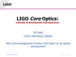
LIGO Core Optics: a decade of development and experience. W. Kells LIGO Laboratory, Caltech With acknowledgement of entire LIGO team for its optical development. LIGO “Core” Optics. 6 (4 test masses; splitter; recycling mirror) large f optics which form high power cavities.

E N D
LIGO Core Optics:a decade of development and experience W. Kells LIGO Laboratory, Caltech With acknowledgement of entire LIGO team for its optical development GWADW 2006
LIGO “Core” Optics • 6 (4 test masses; splitter; recycling mirror) large f optics which form high power cavities. • 11Kgm (f 25cm, h 10cm) • Low loss, low distortion fused silica • Designed (epoch ’94-97) to achieve science requirements: with 6Watt input • Extensive simulations • Protracted “pathfinder” fabrication test pieces • Transition from 535 to 1064nm • Valuable lessons learned from Caltech 40m prototype interferometer GWADW 2006
Major early concerns • Fabrication tolerances: match of optical modes • D ROC of mirrors arm imbalance: excessive “contrast defect” to dark port • D reflectivity, loss • Coating stability and uniformity • Thermal lensing: effect on recycling cavity “point design” • Long term contamination build up on HR surfaces • Uncertain residual Silica bulk absorption. • Static charging on suspended dielectric TMs • Inherent unstable recycling cavity design • Hypersensitivity to polish, coating, homogeneity errors • Effective loss of long cavities with figure distortions • Essential target of “FFT” studies • Coupled with coating reflectivity tolerance: rifo >/< 0 (point design recycling) GWADW 2006
Global surface metrology FFT mirror map localized roughness Optical Loss Expectations • Goal: 30 based on older polish/coating information • Pathfinder development & fabrication proved much better: • Micro roughness srms <0.28 nm prompt loss ~(4 p srms/l)2 <10 ppm • Super polished substrate 2 - 3x lower srms • Simulation (FFT) with Fab. Data: • Figure= modal distortion • Roughness= loss • Low absorption= cold “start up” • Witness sample reflectivity Simulated G (at least: CR field not affected by degenerate recycling) far exceeds goals • Consistent with Advanced ligo requirements H1 ETMy polished surface PSD GWADW 2006
Scatterometer port 5.5 10-8 Sr H1 ETMy Main arm beam ITM FFT map representation k-1 roughness k-2 Scatterometer studies • Observed interferometer gains lower than Sim. predictions. • Consistent with 50-70ppm avg. additional loss per TM. • Consistent with “visibilities” (resonant reflectivity defect) of individual arms • In situ studies: Some HR surfaces viewable @ 3 angles: • Angular dependence more isotropic, “point like” than metrology prediction • In situ observed scatter ~70 ppm mirror • ~same level, character for every TM independent of history/cleaning. GWADW 2006
In Situ Optics Performance • ~41, which is: • Consistent with measured arm visibilities • Consistent with total arm loss dominated by prompt scatter. • Scatterometer data extrapolated to absolute loss • Consistent with lower than anticipated contrast defect ( and small FFT dependence on maps) Replaced ITM GWADW 2006
Resonant arm, Gaussian illuminated ETM Homogeneous roughness ? • Expect isotropic glow from “homogeneous” polish roughness • Find: “point” defect scatter dominates • Bench scans (1064nm) also show excess Is it just dust ?? Reference calibration: known cavity loss GWADW 2006
Analysis of the “Globular Cluster” • Cleanest point scatter image: 2k ETMy: • Grab video stills for detailed analysis: • This point defect background ~same for all optics. • Diffuse (micro roughness) background contributes < 1/3 of total scatter. • Other blemishes don’t dominate total (?) • Puzzle: Why these point defects missed in Lab. QA? Defocused Focused GWADW 2006
Bench scan of removed ITM Coatings sensitive to handling • For several years Hanford 2k performed poorly • X arm visibility (resonant reflectivity) poor • Ugly recycling cavity “mode” pattern • Excess dark port contrast • More dramatic: unlocked arm cavity • Found: AR coating anomaly • Hypothesis: extended harsh cleaning of surfaces had etched coating layers. Lesson: coating sensitivity to thickness change (confirmed by model). GWADW 2006
Contamination & thermal lensing • ~7 years of installed Core optics • No evidence of accumulating contamination (scattering or absorbing) • Routine full lock only ~5 yrs. High power only 1-2 yrs. • Some optics >6 yrs hanging have no evidence of HR absorption >1ppm (design) • Net scatter loss seems independent of TM installation epoch (though high !) • Residual absorption has been found consistent with materials/Fab. expected. • As anticipated by simulations, this level essentially only affects SB fields • Bulk silica absorption not controlled sufficiently for “point” thermal design. • “TCS” system required for compensating residual variations. • This typical experience: extrapolates well to Adv. LIGO ! • Outstanding discrepancy: installed TM scatter loss far too high • Assumed either treatable “dust” issue; or adjustment of coating process • However also contamination accidents • High power operation revealed >10x residual coating absorption • Unique to pair of ITMs: no evidence in other Hanford optics. When ?? GWADW 2006
Mean Abs.= 11.8ppm Normalized Correlation = 0.5 Contamination in LIGO I TMs • Goal: corroborate in situ performance with bench tests • Many LIGO COC optics studied • Comparisons establish “typical” from anomalous • Absolute calibration to various reference mirrors. • Components of “loss test” cavity Example: What is anomalous contaminant on H1 ITMs? • Absorption is lumpy but not point like • Scatter also anomalous and correlates well spatially with absorption • Easily removed by surface cleansing • Fine absorbing dust, sucked in during vent? GWADW 2006
Conclusions, Direction • LIGO I optical performance meets design. • “As built” expectations far exceeded design. • Can be of significant concern for Advanced LIGO, which has initially assumed at least duplicating “as built” performance • Design OTF tests to understand anomalous scatter: • “Frozen” in the coatings ? • Surface contamination (~ common to all installed optics !) • Also apparent cleaning streaks/defects: significant in terms of loss? GWADW 2006
Expectations vs Performance • Expectations: FFT simulations. • Design era (c ’96 ’98). Remarkable agreement with current operations. • “As built” simulations based on bench measurements of actual fabricated optics (c summer ’03) • In Situ measurements (here, fullest story: H1 interferometer) • Scatterometer sampling of in lock beam scatter from HR surfaces. • Arm visibilities (~’00 culminating 11/02) • Operational performance (recycling gains, contrast defect) (to present). • Comparison with super polished H2 ETMs. • Detailed study of HR surface (Image analysis) “beam spots” (10/03) GWADW 2006
“As built” FFT Simulation • FFT simulation of H1 with no free parameters: • “Cold” state: no thermal lens (little effect on CR light) • ~ 92 (observed ~ 41) • FFT uses measured distortion maps,all HR interfaces • minor effect on FFT • ~13% for full as built simulation. Negligible for loss matched case. • Consistent with very good ifo contrast defect • 6 10-4 for H1 • 3 10-5 for L1 • Other in situ observations (e.g H1 arm visibilities) are consistent with arm loss needed to “match” observed . GWADW 2006