Convergent-beam electron diffraction
Convergent-beam electron diffraction. Applications. Bragg’s Law. Applications - in common with spot patterns. 1 Lattice spacings 2 Unit cell 3 Orientation. Applications - special to CBED Established. 1 Crystal symmetry 2 Local strain 3 Direct phase identification 4 Thickness.

Convergent-beam electron diffraction
E N D
Presentation Transcript
Convergent-beam electron diffraction Applications
Applications - in common with spot patterns • 1 Lattice spacings • 2 Unit cell • 3 Orientation
Applications - special to CBEDEstablished • 1 Crystal symmetry • 2 Local strain • 3 Direct phase identification • 4 Thickness
Applications - special to CBEDAdvanced • 1 Crystal structure determination • 2 Bonding measurement • 3 Phase determination • 4 Improved defect analysis
Advanced Techniques • The Tanaka methods • The techniques • LACBED • Other variations (CBIM, SA-CBED) • Applications • Spatial variation • Defect analysis • Other Techniques • Coherent CBED • Energy filtering
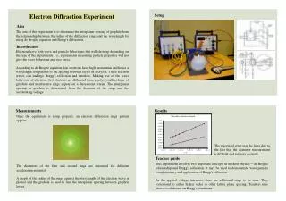
Lattice Spacings The lattice spacing is determined from the distance between the diffracted beams. In spot patterns it is the distance between spots. In convergent-beam patterns it is the distance between discs. These are generally equally accurate.
Unit Cell Determination If a very short camera length is used, the unit cell can be determined, in principle, from a single diffraction pattern. In practice this may be tricky. The centering of the Bravais lattice can be easily obtained at a suitable zone axis.
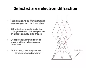
Orientation If the diffraction pattern is indexed, the orientation of the sample is determined. A selected area pattern can determine the orientation to within a few degrees. In convergent-beam diffraction additional information, from details in the discs or from Kikuchi lines, gives the result to a fraction of a degree.
Symmetry The determination of the symmetry of a crystalline specimen is one of the most powerful applications of convergent-beam diffraction. It is valuable both to identify known phases and to determine the symmetry of new phases.
Strain from HOLZ lines • Limitations • The strain must be uniform through the thickness of the specimen. • The result is for the strain in the thin foil - not the strain in the original sample. • Results are relative not absolute without dynamical calculation.
Phase Identification • All convergent-beam zone axis patterns are unique and serve to identify phases. • You must educate your eye. • Limitations • The patterns do change with thickness • The uniqueness is not absolute.
Thickness • The method uses two-beam conditions. • Some care must be taken in the analysis. • The thickness is for the crystalline part of the sample only.
Crystal Structure • The phase problem • Crystal structure determination • Bonding measurement
Because of the complex interference between diffracted beams in dynamical electron diffraction, electron diffraction intensities are very sensitive to small changes in Vg. • Electron diffraction can thus determine bonding electron densities - but the calculations are complicated.
Midgley, Saunders, Vincent and Steeds Ultramicroscopy 59 (1995) 1-13
Midgley, Saunders, Vincent and Steeds Ultramicroscopy 59 (1995) 1-13
The Tanaka Methods • Traditional microscopy taught that the microscope should be focussed on the specimen or on the diffraction pattern in the back focal plane. • Tanaka liberated us and gave rise to a family of new techniques by telling us to look in other places.
Defect Analysis • Large-Angle Convergent-Beam patterns provide an improved method of determining the Burgers vectors of dislocations. (And characterizing other defects.) • The dislocations have to be well separated.