INTEGRATED CIRCUITS
INTEGRATED CIRCUITS. Dr. Esam Yosry. Lec . #7. Introduction Etching Wet Etching Dry Etching Plasma Etching Wet vs. Dry Etching Physical vs. Chemical Processes. Etching. Introduction ( Chip Fabrication Cycle). Introduction ( Processes). Oxidation Diffusion Ion Implantation


INTEGRATED CIRCUITS
E N D
Presentation Transcript
INTEGRATED CIRCUITS Dr. EsamYosry Lec. #7
Introduction • Etching • Wet Etching • Dry Etching • Plasma Etching • Wet vs. Dry Etching • Physical vs. Chemical Processes Etching
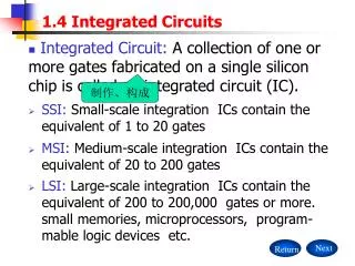
Introduction(Processes) • Oxidation • Diffusion • Ion Implantation • Deposition • Etching • Lithography • Deposition • Removal • Patterning • Modification of electrical properties
Etching • We want to transfer the photoresist pattern to the underlying material. • Removal of material by chemical or physical means is called etching. • Process must be selective to the material you are removing.
Etching • Want faster etches so process is done quicker. • Too fastprocess will be difficult to control. • Ratio of etch rates of other materials referenced to the material you are etching. • Lateral extent of the etch under the resist mask.
Etching • Usually selectivity and directionality are the first order issues. • Selectivity comes from chemistry process. • Directionality comes from physical process. • Modern etching try to optimize both.
Etching • Two main types of etching: Wet and Dry (plasma). • Plasma etching dominates today. • Etching of thin films and sometimes the silicon substrate are very common process steps.
Wet Etching • Wafers submerged in specific chemical baths. • Purpose is to selectively remove materials (Si, SiO2, Al) that are not covered by a Photoresist. • Etch Rate is the rate at which the material is removed (measured in Å/min). • Isotropic Etch proceeds in all directions at the same rate. • Anisotropic Etch is preferential in one direction.
Wet Etching Resist Mask Anisotropic Isotropic Mask Film Insulator Film Semiconductor Substrate hf Isotropic Anisotropic
Wet Etching • Oxide, Poly, and Metal layers are to be etched through a developed PR window. • Wet etchant acids : HNO3, H3PO4 and HF acids. • Wet etching is isotropic (only in large windows).
Wet Etching Substrate Selectivity Etch Stop We want the etchant to remove SiO2 and stop at Si. Stringer When material is cleared from a planar region - residual material remains at steps. Mask SiO2 Si FILM II “Residue” II FILM I FILM I SUBSTRATE SUBSTRATE Prior to Etch Etched to “Endpoint”
Wet Etching Wet Etching Silicon Dioxide • Solution of Hydrofluoric Acid is normally used. Reaction is: SiO2 + 6HF H2 + SiF6 + 2H2O • Etch Rate ~ 1000Å/min at 25°C. Wet Etching Aluminum • Phosphoric Acid is used to etch Aluminum. • The reaction forms Al2O3 which dissolves in water. • Etch rate = 2000Å/min at 25°C
Dry Etching • Removing by exposingthe mask to bombardmentof ions. • The dry etching process typically etches directionally or anisotropically. • Dry etching is useful for materials which are chemically resistant and could not be wet etched. • Dry etchant : Plasma and Reactive Ion Etching. • Dry etching is anisotropic(for small windows).
Dry EtchingPlasma Etching • It is a faster and simplerchemical process. • More directional (anisotropic). • Both chemical and ionic species play a role. • Reactant ions in the RF induced plasma diffuse to the wafer. • Reaction products are volatile: CF4 for Si SiF4 (volatile) CHF3 for SiO2 SiF4+CO2+ HF
Plasma Etching Mechanics • Three mechanisms: • Chemical etching (isotropic, selective). • Physical etching (anisotropic, less selective). • Ion-enhanced etching (anisotropic, selective).
Wet vs. Dry Etching Characteristic Dry Etching Wet Etching cost high low control easy not easy etch rate slow fast selectivity moderate high resolution good fair anisotropy good difficult waste disposal problem low high
Thanks Many thanks to Prof. Hany Fikry and Prof WaelFikry for their useful materials that help me to prepare this presentation.