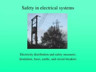
Voltage in Electrical Systems
Voltage in Electrical Systems. 1.3.2. Objectives. Define electric potential, or voltage. Differentiate between AC and DC. Identify the most common source of DC voltage. Describe how to connect DC voltage sources so that voltage will be added.

Voltage in Electrical Systems
E N D
Presentation Transcript
Objectives • Define electric potential, or voltage. • Differentiate between AC and DC. • Identify the most common source of DC voltage. • Describe how to connect DC voltage sources so that voltage will be added.
Recall that a field is a model used to help understand and predict how forces are transmitted from one object to another. • Electric field – electric force per unit charge. Unit is Newton per Coulomb (N/C) Click on this link to go to an electric field simulation from Phet
Electrical Potential • Potential energy – energy of a particle associated with its position.
Electrical Potential • When charges are within an electric field an electrical potential difference is created. • Volt – unit of measurement for potential difference. (electrical potential, voltage) • Voltage is the prime mover in electrical systems (like pressure in fluid system).
Gravitational potential difference – ability to accelerate a mass between two heights. GPE = mgh Electric potential difference (or voltage) – ability to accelerate an electric charge between two points in an electric field. V = E d Units: N•m, or J Units: N•m/C, or J/C (or Volt, V)
Electrical Potential Flow caused by “potential” difference Fluid system Electrical system Current – Flow
Recall, pressure is a prime mover in fluid sytems. Voltage is a prime mover in electrical systems. The flow of charge is called current. Current continues until the plates are neutral.
Pump is used to maintain pressure difference. • A battery is used to maintain a potential difference.
Components of Electrical Systems (fig. 1.37) • Voltage source (battery or generator) • Conductors (wires or circuit board) • Load (motor, lights, etc.) • Control element (switch) Electrical circuit Control Voltage source Electrical Load conductors
Load – an appliance or machine. • Conductor – material through which charge can easily flow. • Control element – a switch that turns the current in the system on or off. • Electrical circuit – closed path for current flow created by connecting voltage sources, conductors, control elements, and loads. Electrical circuit Control Voltage source Electrical Load conductors
Direct Current and Alternating Current • Two types of current (or charge) in electrical systems: • Direct current (DC) – current flows in one direction. • Produced by batteries • Alternating current (AC) – current flows back and forth many time each second. • Produced by alternators
AC vs. DC • Direct Current (DC) – charge flows in one direction. • Batteries • Solar Panels • Alternating Current (AC) – charge flows back and forth. • Alternators • Generators
Cell – single unit that houses on or more chemicals. • Electrons and ions are separated in a cell creating a voltage. • Voltage depends on the chemicals used (Table 1.6). • Battery – a collection of two or more cells connected together. • Battery is “dead” when voltage drops below that required to drive the load. • Types of cells (Figure 1.38) • Primary cell – one-time use. • Secondary cell – rechargeable.
Connecting Cells to Add Their Voltages • Can be added by connecting cells in series, connecting the positive terminal from one cell to the negative terminal of the next cell. • Individual voltages of each cell adds together (Figure 1.39). • In the circuit, electrons move out of the negative terminal/electrode (or cathode) and enter the positive electrode (or anode)
ELECTRICAL SYMBOLS • Wire • Switch • Lamp • Load • Battery • AC power
DC circuit Use this Phet web site link for DC Circuit Construction to download and practice making DC circuits. Click on this Phet web site link for DC Circuit Lab to get more practice with DC circuits
AC Circuits • Positive and negative terminals change many times per second. • Majority at a rate of 60 cycles per second • Cycling rate, called frequency. • Measured in hertz, cycles per second (1/s, or Hz).
AC Circuit Demonstration Click on this Phet web link on AC Current – click on the link, download the program and practice making AC circuits Click on this Phet web link for the AC Current Lab simulation.
Unit is Newton per Coulomb (N/C) Electrical force • SI unit for charge is the Coulomb (C). • Elementary charge of one electron or proton is 1.60 x 10⁻¹⁹C • q1 and q2 are the charges on two objects. • d = distance between charged objects • K = constant = 9.0 x 10⁹ N•m2/C2 Electric field
Voltage E = electric field d = distance Unit is volts V = E x d Electric field Unit is V/m E = V/d distance Unit is meters d = V/E Net Voltage Vnet = Vf – Vi Charge # of electrons x elementary charge 1 electron Unit is Coloumb
Direct current Total voltage is the sum of all voltage sources Vt = V1 + V2 + V3…. Battery + battery + battery – conductor (wire) – load – wire . Alternating current Total voltage is difference between the voltage sources on each side of the load. Vt = V on side one – V on side 2 Battery – conductor – load – battery in reversed position - conductor
ELECTRICAL SYMBOLS • Wire • Switch • Lamp • Load • Battery • AC power