Download
1 / 1
10 likes | 111 Vues
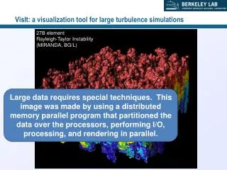
Research group explores synthetic turbulence for hydroacoustic sources generated by turbulence impingement on propeller and turbine blades. Study validates method, applies to complex problems, and computes acoustic signatures. Synthetic turbulence offers realistic eddies for unsteady flows, crucial for engineering challenges in design and modeling. Utilizing boundary conditions is vital for accurate results and reduced computational effort in simulations. Methodology involves precursor simulation, mapping, and synthetic generation to create turbulence for LES. Results show improved velocity profiles with synthetic turbulence. Future applications include hull-propeller geometries and blade-wake interactions for acoustic source derivation.

E N D
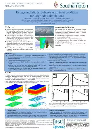
Fluid Structure Interactions Research Group Using synthetic turbulence as an inlet condition for large eddy simulations Thomas P. Lloyd1,2*, Stephen R. Turnock1 and Victor F. Humphrey2 1Fluid Structure Interactions Research Group; 2Institute of Sound and Vibration Research Faculty of Engineering and the Environment, University of Southampton, UK. *T.P.Lloyd@soton.ac.uk Background Motivation and Objectives The current work in motivated by the need to study hydroacoustic sources, generated by the impingement of turbulence on propeller and turbine blades. The main objectives of the work are to: Assess the ability of a ‘synthetic turbulence’ generator to produce realistic eddies; Validate the method using canonical test cases; Apply the technique to more complex problems, such as hydrofoil or propeller flows; Compute the acoustic signature due to the inflow turbulence. • Unsteady flows are commonplace in everyday life. In engineering applications, the existence of unsteady flow phenomena can present challenges in the modelling and design of complex systems. • Two examples of such flows are presented in Figures 1 and 2. In both these cases, the turbulent flow can cause large fluctuating loads which must be accounted for in the design process. • Specifying appropriate boundary conditions for numerical simulations is extremely important to ensure ‘physical’ results and reduce computational effort. • Generally three techniques are available: precursor simulation; mapping; and synthetic generation. Fig. 1: Wind turbine wakes† Fig. 2: Hull-propeller-rudder interaction ‡ Methodology • As initial validation, the channel flow case of Moser et al. [3] is used, where the DNS data has been made available. A Cartesian mesh of ~260,000 cells has been used, with for a friction-velocity based Reynolds number of 395. • Three cases have been computed: • LES1 is a channel flow with cyclic boundaries in the streamwise (x) and spanwise (z) directions; • LES2 uses the inflow generator with U, L and R taken from a RANS simulation; • LES3 use the inflow generator with L taken from a RANS simulation and U and R taken from LES1. • The method of Kornev et al. [1] is employed, which has been applied to the flow around ship sterns [2]. The method produces inhomogeneous, anisotropic turbulence. • The method consists of the following steps: • Conduct a precursor RANS simulation to compute the steady flow field; • Extract the velocity field (U), turbulent length scale (L) and Reynolds stress tensor (R) on an appropriate plane; • Map the extracted data to the inlet of an LES where ‘vortons’ are generated based on these reference fields. Results • It can be observed that the inflow generator (LES2) does not produce the level of fluctuation of the periodic flow (LES1). This led to simulation LES3, since it was found that the RANS simulation does not accurately predict the Reynolds stress tensor in the outer boundary layer ( ) (Fig. 4(b)). • LES3 improves the mean velocity profile compared to LES2, as well as all the components of the rms velocity in the outer boundary layer. (b) (a) (c) (d) Fig. 4: Mean velocity plots: (a) boundary layer profile; rms velocities: (b) streamwise; (c) wall-normal; (d) spanwise. and are the wall-distance and velocity respectively, non-dimensionalised using the friction velocity. Fig. 3: Visualisation of flow: top – velocity; bottom – vorticity magnitude; left – LES1; right – LES2 Conclusions Future Development • The inflow generator performs well for the test case considered here, in terms of both mean velocity and rms velocities. • This method is particularly applicable to more complex cases where the use of periodic boundaries to drive the flow to become turbulent is not possible. • Apply the method to more complex cases. These include hull-propeller geometries and other blade – wake interaction scenarios. • These cases will allow validation in terms of surface pressures and forces, which can be used to derive acoustic sources. References: [1] Kornev, N. and Hassel, E., 2007, “Method of random spots for generation of synthetic inhomogeneous turbulent fields with prescribed autocorrelation function”, Comm. Num. Meth. Eng., 23(1). pp.35-43. [2] Kornev, N., Taranov, E., Shchukin, E., Kleinsorge, L. 2011, “Development of hybrid URANS-LES methods for the flow simulation in the ship stern area” , Ocean Engineering, 38(16), pp. 1831-1838. [3] Moser, R.D., Kim, J. and Mansour N.N., 1999, “Direct numerical simulation of turbulent channel flow up to Reτ=590”, Physics of Fluids, 11(4). pp.943-945. †: www.windbyte.co.uk; ‡: www.sva-potsdam.de/cfd-hull-propulsor-interaction.html FSI Away Day 2012 Acknowledgement: This project is supported by funds from the Defence Science and Technology Laboratory, QinetiQ and the University of Southampton. The Institute of Technical Thermodynamics at the University of Rostock is thanked for supplying the inflow generator code.