Download

1 / 68
1.92k likes | 6.07k Vues
The X-Ray Tube. Bushong Ch 7. X-RAY TUBE. MADE OF THIN PYREX GLASS OR METAL ENCLOSURE TO WITHSTAND HIGH HEAT LOAD AND MINIMIZE X-RAY ABSORPTON IS GAS EVAUCUATED so electrons won’t collide with the air molecules in the tube. THE X-RAY TUBE.

E N D
The X-Ray Tube Bushong Ch 7
X-RAY TUBE • MADE OF THIN PYREX GLASS OR METAL ENCLOSURE TO WITHSTAND HIGH HEAT LOAD AND MINIMIZE X-RAY ABSORPTON • IS GAS EVAUCUATED • so electrons won’t collide with the air molecules in the tube
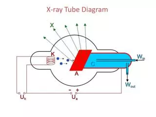
THE X-RAYTUBE • The X-Ray tube is the single most important component of the radiographic system. It is the part that produces the X-rays
Protective housingMade of lead & steel • When x-rays are produced, they are emitted isotropically • Equal intensity in all directions • We only use x-rays emitted through the window or port • Called the useful or primary beam
Protective housing • X-rays that escape through the protective housing are leakage radiation • Provides mechanical support for the tube and protects from rough handling
Protective housing • Some tubes contain oil that serves as an insulator against electric shock and as a thermal cushion • Dissipate heat • Some protective housing has cooling fan to air-cool the tube and oil
Internal components Cathode • The negative side of the tube and has two primary parts • A filament and focusing cup • Filament = a coil of wire about 2mm in diameter and 1 or 2 cm long.
Cathode • Filament • Dual-filament • Focusing cup • Negatively charged
Tungsten • Filaments are usually made of tungsten • Tungsten provides higher thermionic emission than other metals • Tungsten has a very high melting point
Filament • When current (mA) is applied to the coil of wire electron are ejected • The outer-shell electrons of the filament atom are “boiled off”. • This is known as thermionic emission
Focusing cup • The filament is embedded in a metal cup that has a negative charge • Boiled off e- tend to spread out due to electrostatic repulsion. The focusing cup confines the e- cloud to a small area
Filament Current • When the x-ray imaging system is first turned on, a low current passes through the filament to warm it and prepare it for the thermal jolt necessary for x-ray production • The current is not enough to energize the tube, just warm the wire of the filament
Space-charge effect • The cloud of e- = space charge • As the space charge becomes more negative by the boiling off of more electrons it makes it difficult for more e- to be emitted • Electrostatic repulsion • Space-charge effect • Space-charge limiting at low kVp & high mA
Dual-focus tubes • Most diagnostic tubes have two focal spots; large & small • Large is used when large body parts are imaged • Small is used when better spatial resolution is desired – better detail • Filament size
Anode • Anode is the positive side of the x-ray tube • The anode conducts electricity, radiates heat and contains the target • Two types of anodes • Stationary & Rotating
Stationary Anode • Used for dental x-rays, some portable imaging • Used when high tube current and power are not required because they are not capable of producing high-intensity x-ray beams in a short time
Anode Function • Mechanical support for the target • Dissipates heat • 99% of the kinetic energy from the e- is converted into heat; 1% is converted into x-rays • Copper, molybdenum and graphite are common anode material
Target • Is the area of the anode struck by the e-from the cathode • Tungsten is the material of choice for the target in general radiography
Rotating Anode • Is powered by an induction motor • The stator is on the outside of the glass, consist of a series of electromagnets • The rotor is a shaft made of bars of copper and soft iron built into one mass
Electromagnetic induction • As current is applied to the stator sequentially so the magnetic field rotates on the axis of the stator • This magnetic field interacts with the metal (ferromagnetic rotor) causing it to rotate in unison with the magnetic field of the stator
Electromagnetic Induction Motor • Anode speed • Average 3,600 rpm (revolutions per minute) • High capacity 10,000 rpm • Anode Cooling Chart • Heat Units (HU)
Dead-man switch • Rotor/Prep – applies current (mA) to the tube • Allows rotor to accelerate to its designed RPM. Rotor stops about 1 min after exposure • Filament current is increased to create e-cloud • Exposure – applies voltage (kV) to make exposure
Focal spot • The area of the anode’s target where x-rays are emitted • The smaller the focal spot the better the resolution of the resultant image
Focal spot • Unfortunately, as the size of the focal spot decreases, the heat of the target is concentrated into a smaller area • This is the limiting factor to focal spot size
Line-focus principle • By angling the target, the effective area of the target is much smaller than the actual area of electron interaction
Line-focus principle • Effective Focal Spot
Target angle • The smaller the target angle the smaller the effective focal spot • Angles from 5 degrees to 15 degrees • Biangular targets are available that produce two focal spot sizes
The second factor of effective focal spot is the incoming size of e- stream
Anode Heel Effect • Because of the use of line-focus principle the consequence is that the radiation intensity on the cathode side of the x-ray field is higher than that on the anode side • “Fat Cat”