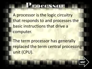
ARM7TDMI Processor
ARM7TDMI Processor. ARM7TDMI processor. The ARM7TDMI processor is a member of the Advanced RISC machine family of general purpose 32-bit microprocessor What does mean ARM7TDMI ? ARM7 - 32-bit Advanced RISC Machine T - Thumb architecture extension

ARM7TDMI Processor
E N D
Presentation Transcript
ARM7TDMI processor • The ARM7TDMI processor is a member of the Advanced RISC machine family of general purpose 32-bit microprocessor • What does mean ARM7TDMI ? ARM7 - 32-bit Advanced RISC Machine T - Thumb architecture extension • Two separate instruction sets, 32-bit ARM instructions and 16-bit Thumb instructions D - Debug extension M - Enhanced multiplier I - Embedded ICE macrocell extension
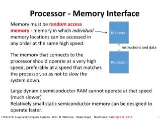
ARM7TDMI Block Diagram • Von Neumann Architecture • 3-stage pipeline • fetch, decode, execute • 32-bit Data Bus • 32-bit Address Bus • 37 32-bit registers • 32-bit ARM instruction set • 16-bit THUMB instruction set • 32x8 Multiplier • Barrel Shifter
ARM7TDMI Operating States • The ARM7TDMI processor has two operating states: • ARM state which executes 32-bit, word aligned ARM instructions • THUMB state which can execute 16-bit, halfword aligned THUMB instructions • Switching state • Entering THUMB state • BX instruction with the state bit (bit 0) set in the operand register. • Automatically on return from an exception (IRQ, FIQ, ABORT, SWI,…), if the exception was entered with the processor in THUMB state. • Entering ARM state • BX instruction with the state bit clear in the operand register. • Automatically on the processor taking an exception. In this case, the PC is placed in the exception mode’s link register.
ARM7TDMI Operating Modes • The ARM7TDMI supports seven modes of operation: • User (usr): The normal ARM program execution state • FIQ (fiq): Designed to support a data transfer or channel process • IRQ (irq): Used for general-purpose interrupt handling • Supervisor (svc): Protected mode for the operating system • Abort mode (abt): Entered after a data or instruction prefetch abort • System (sys): A privileged user mode for the operating system • Undefined (und): Entered when an undefined instruction is executed • Mode changes may be made under software control, or may be brought about by external interrupts or exception processing. • Most application programs will execute in User mode. The non-user modes' known as privileged modes-are entered in order to service interrupts or exceptions, or to access protected resources.
ARM7TDMI Registers • The ARM7TDMI has a total of 37 registers: • 31 general-purpose 32-bit registers • 6 status registers • These registers cannot all be seen at once. The processor state and operating mode dictate which registers are available to the programmer.
Relationship between ARM and THUMB state registers • The THUMB state registers relate to the ARM state registers in the following way:
Program Status Registers (1/3) • The ARM7TDMI contains a Current Program Status Register (CPSR), plus five Saved Program Status Registers (SPSRs) for use by exception handlers. • These register's functions are: • Hold information about the most recently performed ALU operation • Control the enabling and disabling of interrupts • Set the processor operating mode
Program Status Registers (2/3) • Condition Code Flags • The N, Z, C and V bits may be changed as a result of arithmetic and logical operations, and may be tested to determine whether an instruction should be executed • In ARM state, all instructions may be executed conditionally. • In THUMB state, only the Branch instruction is capable of conditional execution. • Control Bits • The I, F, T and M[4:0]) bits will be changed when an exception arises. If the processor is operating in a privileged mode, they can also be manipulated by software. • T bit: • This reflects the operating state. When this bit is set, the processor is executing in THUMB state, otherwise it is executing in ARM state. This is reflected on the TBIT external signal. • Note that the software must never change the state of the TBIT in the CPSR. If this happens, the processor will enter an unpredictable state.
Program Status Registers (3/3) • Control Bits • Interrupt disable bits: • The I and F bits are the interrupt disable bits. When set, these disable the IRQ and FIQ interrupts respectively. • Mode bits: • The M4, M3, M2, M1 and M0 bits (M[4:0]) are the mode bits. These determine the processor's operating mode. Not all combinations of the mode bits define a valid processor mode. Only those explicitly described shall be used. The user should be aware that if any illegal value is programmed into the mode bits, M[4:0], then the processor will enter an unrecoverable state. If this occurs, reset should be applied.
Exceptions (1/6) • Exceptions arise whenever the normal flow of a program has to be halted temporarily • For example to service an interrupt from a peripheral. • ARM supports 7 types of exception and has a privileged processor mode for each type of exception. • ARM Exception vectors
Exceptions (2/6) • When handling an exception, the ARM7TDMI: • Preserves the address of the next instruction in the appropriate Link Register • Copies the CPSR into the appropriate SPSR • Forces the CPSR mode bits to a value which depends on the exception • Forces the PC to fetch the next instruction from the relevant exception vector • It may also set the interrupt disable flags to prevent otherwise unmanageable nestings of exceptions. • If the processor is in THUMB state when an exception occurs, it will automatically switch into ARM state when the PC is loaded with the exception vector address.
Exceptions (3/6) • On completion, the exception handler: • Moves the Link Register, minus an offset where appropriate, to the PC. (The offset will vary depending on the type of exception.) • Copies the SPSR back to the CPSR • Clears the interrupt disable flags, if they were set on entry
Exceptions (4/6) • Reset • When the processor’s Reset input is asserted • CPSR Supervisor + I + F • PC 0x00000000 • Undefined Instruction • If an attempt is made to execute an instruction that is undefined • LR_undef Undefined Instruction Address + #4 • PC 0x00000004, CPSR Undefined + I • Return with : MOVS pc, lr • Prefetch Abort • Instruction fetch memory abort, invalid fetched instruction • LR_abt Aborted Instruction Address + #4, SPSR_abt CPSR • PC 0x0000000C, CPSR Abort + I • Return with : SUBS pc, lr, #4
Exceptions (5/6) • Data Abort • Data access memory abort, invalid data • LR_abt Aborted Instruction + #8, SPSR_abt CPSR • PC 0x00000010, CPSR Abort + I • Return with : SUBS pc, lr, #4 or SUBS pc, lr, #8 • Software Interrupt • Enters Supervisor mode • LR_svc SWI Address + #4, SPSR_svc CPSR • PC 0x00000008, CPSR Supervisor + I • Return with : MOV pc, lr
Exceptions (6/6) • Interrupt Request • Externally generated by asserting the processor’s IRQ input • LR_irq PC - #4, SPSR_irq CPSR • PC 0x00000018, CPSR Interrupt + I • Return with : SUBS pc, lr, #4 • Fast Interrupt Request • Externally generated by asserting the processor’s FIQ input • LR_fiq PC - #4, SPSR_fiq CPSR • PC 0x0000001C, CPSR Fast Interrupt + I + F • Return with : SUBS pc, lr, #4 • Handler @0x1C speeds up the response time
Condition Field (1/2) • All ARM instructions can be conditionally executed, which means that their execution may or may not take place depending on the values of values of the N, C, C and V flags in the CPSR • Every instruction contains a 4-bit condition code field in bits 31 to 28
Condition Field (2/2) • There are fifteen different conditions, each represented by a two-character suffix that can be appended to the instruction's mnemonic. • A Branch (B in assembly) becomes BEQ for "Branch if Equal", which means the Branch will only be taken if the Z flag is set.
Branch Instructions (1/2) • All ARM Processors support a branch instruction that allows a conditional branch forwards or backwards up to 32Mbytes. • As the Program Counter (PC) is one of the general-purpose registers (register 15), a branch or jump can also be generated by writing a value to register 15. • A subroutine call is a variant of the standard branch, the Branch with Link instruction preserves the address of the instruction after the branch (the return address) in register 14 (link register or LR). • A load instruction provides a way to branch anywhere in the 4Gbyte address space. A 32-bit value is loaded directly from memory into the PC, causing a branch. • The ARM7TDMI processor that support the Thumb instruction set also support a branch instruction (BX) that jumps to a given address, and optionally switches executing Thumb instructions.
Branch Instructions (2/2) • List of branch instructions B, BL Branch, and branch with link BX Branch and exchange instruction set • Examples B label ; branch unconditionally to label BCC label ; branch to label if carry flag is clear BEQ label ; branch to label if zero flag is set MOV PC, #0 ; R15 = 0, branch to location zero BL func ; subroutine call to function func MOV PC, LR ; R15=R14, return to instruction after the BL MOV LR, PC ; store the address of the instruction after the next one into R14 LDR PC, =func ; load a 32-bit value into the program counter
Data Processing (1/2) • ARM has 16 data processing instructions. Most data processing instructions take two source operands (Move and Move Not have only one operand) and store a result in a register (except for the Compare and Test instructions which only update the condition codes) • Of the two source operands, one is always a register, the other is called a shifter operand, and is either an immediate value or a register. If the second operand is a register value, it may have a shift applied to it before it is used as the operand to the ALU
Data Processing (2/2) • List of data processing instructions
Multiply Instructions (1/2) • ARM has two classes of multiply instruction • normal, 32-bit result • long, 64-bit result • All multiply instructions take two register operands as the input to the multiplier • ARM does not directly support a multiply by constant instruction due to the efficiency of shift and add, or shift and reverse subtract instructions • There are two multiply instructions that produce 32-bit results • MUL, multiplies the values of two registers together, truncates the result to 32 bits, and stores the result in a third register. • MLA, multiplies the values of two registers together, adds the value of a third register, truncates the result to 32 bits, and stores the result into a fourth register (multiply and accumulate) MUL R4, R2, R1 ; Set R4 to value of R2 multiplied by R1 MULS R4, R2, R1 ; R4 = R2xR1, set N and Z flags MLA R7, R8, R9, R3 ; R7 = R8xR9 + R3
Multiply Instructions (2/2) • There are four multiply instructions that produce 64-bit results (long multiply) • Two of the variants multiply the values of two registers together and store the 64-bit result in a third and fourth register. There are a signed (SMULL) and unsigned (UMULL) variants. • The remaining two variants multiply the values of two registers together, add the 64-bit value from a third and fourth register and store the 64-bit result back into those registers (third and fourth). There are also signed (SMLAL) and unsigned (UMLAL) variants. These instructions perform a long multiply and accumulate SMULL R4, R8, R2, R3 ; R4 = bits 0 to 31 of R2xR3 ; R8 = bits 32 to 63 of R2 x R3UMULL R6, R8, R0, R1 ; R6, R8 = R0 x R1UMLAL R5, R8, R0, R1 ; R5, R8 = R0 x R1 + R5, R8
Load and Store Instructions (1/2) • Load and store instruction come in three types: • load or store the value of a single register • load and store multiple register values • swap a register value with the value of a memory location • Load and store single register • Load register instructions can load a 32-bit word, a 16-bit halfword or an 8-bit byte from memory into a register. • Store register instructions can store a 32-bit word, a 16-bit halfword or an 8-bit byte from a register to memory. • List of load and store single register: • LDR/STR, Load/Store word • LDRB/STRB, Load/Store byte • LDRH/STRH, Load/Store unsigned halfword • LDRSB, Load signed byte • LDRSH, Load signed halfword
Load and Store Instructions (2/2) • Load and Store multiple registers • Load and Store multiple instructions perform a block transfer of any number of the general purpose registers to or from memory • Four addressing modes are provided: • pre-increment • post-increment • pre-decrement • post-decrement • List of load and store multiple instructions • LDM, Load multiple • STM, Store multiple • Swap a register value with the value of a memory location • Swap can load a value from a register-specified memory location, store the contents of a register to the same memory location, then write the loaded value to a register. • List of semaphore instructions • SWP, Swap • SWPB, Swap Byte
SWI : Software Interrupt • The Software Interrupt instruction enters supervisor mode in a controlled manner: • The instruction causes the software interrupt trap to be taken, which effects the mode change • If the SWI vector address is suitably protected (by external memory management hardware) from modification by the user, a fully protected operating system may be constructed. • The bottom 24 bits of the instruction are ignored by the processor, and may be used to communicate information to the supervisor code.
How Does Thumb Work ? • The Thumb instruction set is a subset of the ARM instruction set, optimized for code density. • Almost every Thumb instructions have an ARM instructions equivalent: • ADD Rd, #Offset8 <> ADDS Rd, Rd, #Offset8 • Inline expansion of Thumb Instruction to ARM Instruction • Real time decompression • Thumb instructions are not actually executed on the core • The core needs to know whether it is reading Thumb instructions or ARM instructions. • Core has two execution states - ARM and Thumb • Core does not have a mixed 16 and 32 bit instruction set.
THUMB: ADD Rd,#Constant 15 0 0 0 1 1 0 Rd Constant Major opcode Always condition Minor opcode Destination & source register Zero extended constant 31 11 8 7 0 28 24 21 20 19 16 15 12 1 1 1 0 0 0 1 0 1 0 0 1 0 Rd 0 Rd 0 0 0 0 Constant I op1+op2 S ARM: ADDS Rd, Rd, #Constant Thumb Instruction Set Decompression
Branch Instructions • Thumb supports four types of branch instruction: • an unconditional branch that allows a forward or backward branch of up to 2Kbytes • a conditional branch to allow forward and backward branches of up to 256 bytes • a branch with link is supported with a pair of instructions that allow forward and backwards branches of up to 4Mbytes • a branch and exchange instruction branches to an address in a register and optionally switches to ARM code execution • List of branch instructions • B conditional branch • B unconditional branch • BL Branch with link • BX Branch and exchange instruction set
Data Processing Instructions • Thumb data-processing instructions are a subset of the ARM data-processing instructions • All Thumb data-processing instructions set the condition codes • List of data-processing instructions • ADC, Add with Carry • ADD, Add • AND, Logical AND • ASR, Arithmetic shift right • BIC, Bit clear • CMN, Compare negative • CMP, Compare • EOR, Exclusive OR • LSL, Logical shift left • LSR, Logical shift right • MOV, Move • MUL, Multiply • MVN, Move NOT • NEG, Negate • ORR, Logical OR • ROR, Rotate Right • SBC, Subtract with Carry • SUB, Subtract • TST, Test
Load and Store Register Instructions • Thumb supports 8 types of load and store register instructions • List of load and store register instructions • LDR Load word • LDRB Load unsigned byte • LDRH Load unsigned halfword • LDRSB Load signed byte • LDRSH Load signed halfword • STR Store word • STRB Store byte • STRH Store halfword
Load and Store Multiple Instructions • Thumb supports four types of load and store multiple instructions • Two (a load and store) are designed to support block copy • The other two instructions (called PUSH and POP) implement a full descending stack, and the stack pointer is used as the base register • List of load and store multiple instructions • LDM Load multiple • POP Pop multiple • PUSH Push multiple • STM Store multiple
60% 65% 70% 75% % of ARM code size Code size • Generally, routines in THUMB code are between 65 and 70% the size of the equivalent ARM code.
Arm Instruction Set Advantages • All instructions are 32 bits long. • Most instructions are executed in one single cycle. • Every instructions can be conditionally executed. • A load/store architecture • Data processing instructions act only on registers • Three operand format • Combined ALU and shifter for high speed bit manipulation • Specific memory access instructions with powerful auto-indexing addressing modes • 32 bit ,16 bit and 8 bit data types • Flexible multiple register load and store instructions
Thumb Instruction Set Advantages • All instructions are exactly 16 bits long to improve code density over other 32-bit architectures • The Thumb architecture still uses a 32-bit core, with: • 32-bit address space • 32-bit registers • 32-bit shifter and ALU • 32-bit memory transfer • Gives.... • Long branch range • Powerful arithmetic operations • Large address space