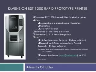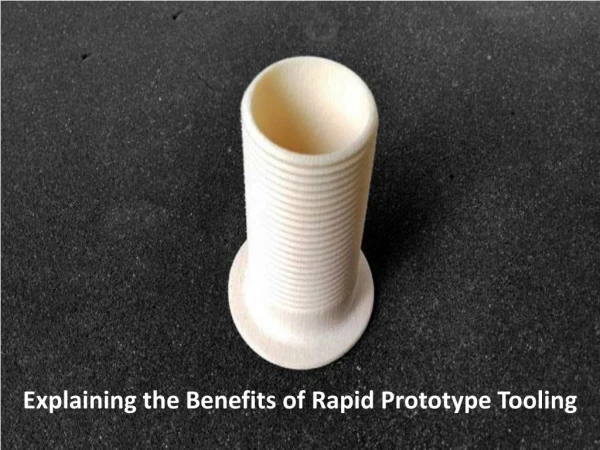
d imension BST 1200 Rapid Prototype Printer
180 likes | 312 Vues
d imension BST 1200 Rapid Prototype Printer. Located in GJ 115 Cost: $25 set-up fees as well as $10/in 3 material To build, contact Russ Porter ( russp@uidaho.edu ). Rapid Prototype Machine (RPM). The dimension BST 1200 is an additive fabrication printer

d imension BST 1200 Rapid Prototype Printer
E N D
Presentation Transcript
dimension BST 1200 Rapid Prototype Printer • Located in GJ 115 • Cost: $25 set-up fees as well as $10/in3 material • To build, contact Russ Porter (russp@uidaho.edu)
Rapid Prototype Machine (RPM) • The dimension BST 1200 is an additive fabrication printer • Additive fabrication is a process in which layers of material are placed successively on top of each other to create the component. The highest tolerance that can be achieved in the dimension is 0.01 inches, due to filament thickness. • Uses: • Allows for inexpensive pre-production part inspection • Helps in marketing • Assists in concept evaluation • NOTE: The printer takes 40 minutes to warm-up so plan accordingly.
File Set-up • Save the part file as a .stl file, in it’s parent program. • When printing an assembly save the assembly as a single part, then as a .stl, or it will save each component of the assembly as a .stl file. • CAUTION: This assembly is not functional, as the printer only has the ability to lay down external geometries. • To print an assembly, print each part separately and assemble.
Printing Prep • Before turning the machine on, plug the network cable from the computer into the RPM. • Then turn on the RPM. The switch is located on the front lower right of the printer. It will take three to seven minutes to boot. Remember that it takes 40 minutes to warm-up. • When it’s ready the printer status should say “Idle.” • Next open CatalystEX on the computer. • Make sure that the printer and computer are communicating.
Printing Prep • To insert a modeling base, turn the two retainer clips on the front of the Z-Platform down. • Place the modeling base so that the tabs on the base align with the slots in Z-Platform. • Slide the base towards the back of the unit, until the front edge of the base is flush with the front of the unit. • Secure the base by turning the two retaining clips up. • NOTE: Do not touch the top surface of the modeling base when installing. Grease and oil cause poor adhesion. Retaining Clips
Part Set-up • Click File, then open the .stl file in CatalystEX. • Choose the interior and structural material settings that best suit your needs. • MAKE SURE YOU SELECT THE CORRECT UNITS.
Part Set-up • Click on the “Orientation” tab. The “Auto Orient” button can be used if you’re unsure of which orientation to choose. • Or use the rotation button for each axis so that the surface area of the part on the base is maximized, requiring less structural filler. • Once the part is oriented, click on the “Add to Pack” button on the bottom
Part Set-up • Now click on the “Pack” tab. • CatalystEX has a default pack set-up that does not allow parts to occupy more than their “area,” signified by the green square around the part when it is clicked on. • To move parts, just click and drag the shape.
Part Set-up • To place parts closer together, click on the “Allow Nesting” box. • This allows parts to be placed such that their footprints don’t overlap. • Orient the parts close together, to minimize travel, and ultimately build time. • Make sure to leave some space to allow air flow.
Printing • Once the part is oriented properly in the pack, move to the printer. • At the printer, press the “Wait for Part” button. • After ensuring that an empty modeling base is installed answer “Yes” to the prompt “Is Model Base Installed?” • In CatalystEX click the print.
Refilling the Printer • If the build needs more material than the printer has, then replacing the material will be necessary. • This will be evident by looking at the screen on the printer, and looking at the amount of material needed to create the part, which comes from CatalystEX. • Each cartridge contains 56.3 in3 of material.
Refilling the Printer • To do so, get a new cartridge and remove the red plug by turning a quarter turn clockwise, and lifting. • Find the end of the material filament taped with a “flag.” • Be careful not to touch the pinch roller on the side of the cartridge, or material can be drawn into the cartridge.
Refilling the Printer • Pull the first 12 inches of material out of the cartridge, and cut it flush against the cartridge with scissors. • Press the “Material Load” button on the front of the printer.
Refilling the Printer • The old cartridges are located on the lower front of the machine, below the door. • Replace the cartridges in their appropriate slots by gently pressing the old cartridge forward, and then gently pulling it out of the slot. • There will be approximately seven feet of filament that needs to be pulled from the system. The model cartridge goes on top and the structural filler on bottom.
Refilling the Printer • Press the load button to load material. • When loading, watch the extrusion tip to see that it clears. The display panel will display “Did Model Material Purge.” Press the purge again button to ensure that it did. • Repeat this process for the structural material. • If this was done mid-build press the resume button to resume printing. Support Tip Model Tip
Post-Print • After printing, remove the base. It is best to remove the parts from the base while it is still warm. To do so grab diagonal corners of the board, and flex to free the part. • To remove the structural filler, it is easiest to just try and pop it off with your fingers. If there are some parts that you can’t remove, carefully use a razor blade to cut the excess off.
Post-Print • After every build it is necessary to empty the junk material, located at the right rear of the inside of the printer. Just slide the canister up off it’s pegs, empty and replace. • Shut off the printer, and return the base to storage.
Example Swinglink for bicycle suspension