COMPUTED TOMOGRAPHY
COMPUTED TOMOGRAPHY. Merrill’s V. 3: Ch. 31 & Bushong Ch. 23 . No other development in x-ray imaging over the past 50 years has been as significant !. Snook transformer Coolidge hot-cathode x-ray tube Potter-Bucky diaphragm Image-intensifier tube. Wow… look at that image

COMPUTED TOMOGRAPHY
E N D
Presentation Transcript
COMPUTED TOMOGRAPHY Merrill’s V. 3: Ch. 31 & Bushong Ch. 23
No other development in x-ray imaging over the past 50 years has been as significant ! • Snook transformer • Coolidge hot-cathode x-ray tube • Potter-Bucky diaphragm • Image-intensifier tube Wow… look at that image quality & detail
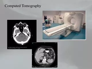
FUNDAMENTALS • CREATING A CROSS-SECTIONAL TOMOGRAPHIC PLANE OF ANY BODY PART • A PATIENT IS SCANNED BY AN X-RAY TUBE ROTATING AROUND THE BODY • A DETECTOR ASSEMBLY MEASURES THE RADITION EXITING THE PATIENT.
Tomo = image // to long axis of the bodyCT = image is transverse to the body
In its simplest form, a CT imaging system consists of a finely collimated x-ray beam and a single detector. • both moving synchronously in a translate rotate mode. • Translation = one rotation of source and detector
FUNDAMENTALS • EXITING RADIATION: PRIMARY DATA • PRIMARY DATA IS COLLECT BY DETECTORS • THE COMPUTER COMPILES AND CALCULATES THE DATA BASED ON PRESELECTED ALGORITHM AND AN IMAGE IS FORMED
IMAGE • EACH IMAGE IS DISPLAYED IN AN AXIAL FORM INITALLY • THE IMAGES ARE DISPLAYED ON A CATHODE RAY TUBE (CRT) OR LCD
Cathode Ray Tube (CRT): is an air evacuated glass envelope containing an e- gun and a fluorescent screen. When e- hit the fluorescent screen light is emitted
CT • Conventional Radiographs: Frequently body structures are superimposed • In CT: A tightly collimated x-ray beam is directed thought the patient from different angles – “cross sectional image” • Essentially eliminating superimposition of body structures
CT • Claim to fame: Exceptional Contrast Resolution
Contrast resolution = differentiation of densities, capable of differentiating among tissues with similar densities
The contrast of an object is expressed relative to its surrounding background. That is what determines its visibility.
CT • Due to the reduction in amount of scattered radiation • Reducing over lapping structures and 2 collimators • Digitized image: because of this numerous image manipulation techniques can be used to enhance and optimize the diagnostic information. • Window/Level, Axial, Sagittal, Coronal
Historical Development • CT was first demonstrated successfully in 1970. Dedicated to head CT only • Dr. Godfrey Hounsfield (Engineer) • Allan Macleod Cormack (Nuclear Physicist) • Nobel Prize in medicine and physiology in 1979
First full-scale commercial unit • Installed in 1971 • Physicians recognized its value for providing diagnostic neurologic information • U.S.– June 1973 at the Mayo Clinic (MN) & General Hospital (MA) • These early units were also dedicated head CT scanners.
Early CAT scanners • Hounsfield’s discovery parallels Rontgen’s discover of x-rays • Early CAT scans required nine days to produce a single section image
Whole-body scanners • 1974 – Dr. Robert S. Ledley of Georgetown University Medical Center, developed the first whole-body scanner • Many different companies began manufacturing scanners.
Generations • First Generation Scanners • Translation/Rotation • Tube produced a finely collimated beam or pencil beam • 1 to 3 detectors were placed opposite the tube for radiation detection • 4.5 minutes to gather enough information for one slice • Tube was only able to rotate 180 degrees
Second Generation • Fan-shaped x-ray beam • 30 or more detectors • 20 seconds per slice or 10 minutes for a 40 slice exam • 180 degree rotation • Long data reconstruction time
Third Generation • Fan-shaped x-ray beam • 960 detectors opposite the x-ray tube • Complete 360 degree rotation Rotate/Rotate movement • One rotation = one slice • Second data acquisition could be made as the tube and detectors move in the opposite direction. • Time reduced to 1 sec per slice
Fourth Generation • Developed in 1980’s • Fixed ring of as many as 4800 detectors, completely surrounding the patient, Rotate only movement • Rotating x-ray tube provides short bursts of radiation • Detectors collect the remnant radiation to reconstruct into an image • 1 minute for multiple slices
Modern Scanners • No longer categorize into Generations • Contemporary CT scanners are either third or fourth generation designs • Scanners are categorized by tube and detector movement • Slip Ring Technology: connects generator with tube (no cables)
Technical Aspects • Optimum imaging: patient/area of interest and gantry are perpendicular to each other • Tube rotates around the patient, irradiating the area of interest. • Detectors measure the transmitted x-ray values, covert them in to an electric signal, and relay the signal to the computer.
Raw Data • The remnant radiation that is converted into an electrical signal values are called projections, scan profiles or raw data. • Raw data is collected and digitized. • This process assigns a whole number to each signal. • The value assigned is directly proportional to the strength of the signal.
Digital Image • Array of numbers arranged in a grid of rows and columns called a matrix. • Single square, or picture element, with in the matrix is called a pixel. • Slice thickness gives the pixel and added dimension called the volume element, or voxel
Voxel • Each pixel in the image corresponds to the volume of tissue in the body section being imaged. • The voxel volume is a product of the pixel area and slice thickness