
Instruction Execution Cycle
E N D
Presentation Transcript
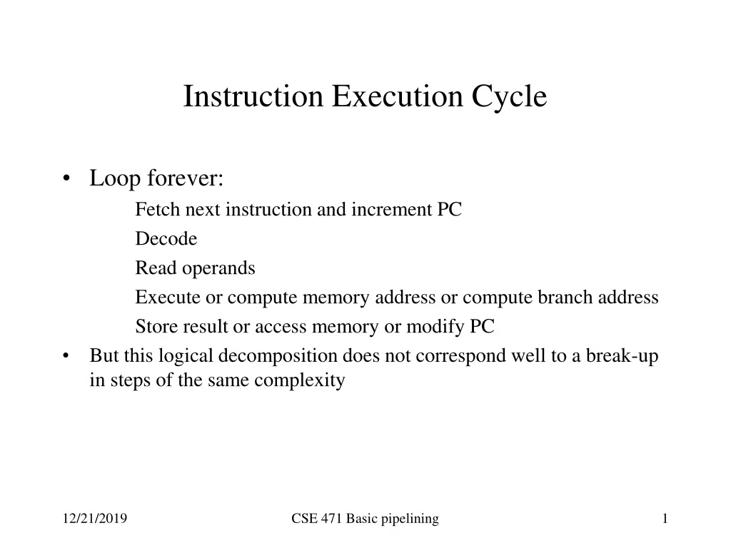
Instruction Execution Cycle • Loop forever: Fetch next instruction and increment PC Decode Read operands Execute or compute memory address or compute branch address Store result or access memory or modify PC • But this logical decomposition does not correspond well to a break-up in steps of the same complexity CSE 471 Basic pipelining
Pipelining • One instruction/result every cycle (ideal) Not in practice because of hazards (data dependencies, control flow dependencies) • Throughput vs. latency Throughput = number of results/second. Latency = time to execute a given instruction • Speed-up of pipleining vs. non-pipelined version In the ideal case, if n stages , the speed-up will be close to n Can’t make n too large: load balancing between stages & hazards CSE 471 Basic pipelining
Basic pipeline implementation • Five stages: IF, ID, EXE, MEM, WB • What are the resources needed and where ALU’s, Registers, Multiplexers, Decoders, Sign extenders etc. (we’ll see Verilog versions of these) • What info. is to be passed between stages Requires pipeline registers between stages: IF/ID, ID/EXE, EXE/MEM and MEM/WB What is stored in these pipeline registers (data and control)? • Design of the control unit. CSE 471 Basic pipelining
Basic datapath pipelining • Cf . Fig 6.25 CSE 471 Basic pipelining
Control (ideal case) • Control signals are split among the 5 stages. For the ideal case no need for additional control (but just wait!) • Stage 1: nothing special to control • read instr. memory and increment PC asserted at each cycle • Stage 2: nothing. All instructions do the same • Stage 3: Instruction dependent • Control signals for ALU sources and ALUop • Control signal for Regdest so the right name is passed along • Stage 4: Control for memory (read/write) and for branches • Stage 5: Control for source of what to write in the destination register CSE 471 Basic pipelining
Control unit (simple case) • Cf. Fig 6.30 CSE 471 Basic pipelining
Hazards • Structural hazards Resource conflict (mostly in multiple issue machines; see later in the quarter) • Data dependencies (most common RAW but also WAR and WAW in OOO execution; see later) • Control hazards Branches and other flow of control disruptions • Consequence: stalls in the pipeline CSE 471 Basic pipelining
Pipeline speed-up CSE 471 Basic pipelining
Example of structural hazard • For single issue machine: common data and instruction memory (unified cache) Pipeline stall every load-store instruction (control easy to implement) • Better solutions Instruction buffers Separate I-cache and D-cache Both + sophisticated instruction fetch unit! CSE 471 Basic pipelining
Data hazards • Instruction tries to read a register in stage 2 (ID) and this register will be written by a previous instruction that has not yet reached stage 5 (WB) • Dependencies can occur between • Arithmetic operations • Load and arithmetic operations • The above are RAW (Read After Write) dependencies. CSE 471 Basic pipelining
Data hazards (Example) • For single pipeline in order issue: Read After Write hazard (RAW) Add R1, R2, R3 #R1 is result register Sub R4, R1,R2 #conflict with R1 Add R3, R5, R1 #conflict with R1 Or R6,R1,R2 #conflict with R1 # but OK since R1 stored in # first half of the cycle Add R5, R2, R1 #No conflict CSE 471 Basic pipelining
IF ID EXE MEM WB R1 available here Add R1, R2, R3 | | | | | | R 1 needed here Sub R4,R1,R2 | | | | | | ADD R3,R5,R1 | | | | | | OK OR R6,R1,R2 | | | | | | OK Add R5,R1,R2 | | | | | | CSE 471 Basic pipelining
Resolving data dependencies • Generate code to insert no-ops at the right place • Too complex for modern processors • However compiler optimizations to reduce the number of dependencies are welcome! • Forwarding (see in a couple of slides) • Use register renaming for WAR and WAW hazards (see later in the class) • Stall the pipeline when hardware detects a dependency CSE 471 Basic pipelining
Forwarding between arithmetic instructions • Result of ALU operation is known at end of EXE stage • Forwarding between: EXE/MEM pipeline register to ALUinput for instructions i and i + 1 MEM/WB pipeline register to ALUinput for instructions i and i + 2 Forwarding through register file (write 1st half of cycle, read 2nd half of cycle) for instructions i and i + 3 CSE 471 Basic pipelining
IF ID EXE MEM WB R1 available here Add R1, R2, R3 | | | | | | R 1 needed here Sub R4,R1,R2 | | | | | | ADD R3,R5,R1 | | | | | | OK w/o forwarding OR R6,R1,R2 | | | | | | OK w/o forwarding Add R5,R1,R2 | | | | | | CSE 471 Basic pipelining
Other data hazards • Write After Write (WAW). Can happen in Pipelines with more than one write stage More than one functional unit with different latencies (see later) Use of Register renaming • Write After Read (WAR). Very rare With VAX-like autoincrement addressing modes CSE 471 Basic pipelining
Forwarding cannot solve all conflicts • At least in our simple MIPS-like pipeline Lw R1, 0(R2) #Result at end of MEM stage Sub R4, R1,R2 #conflict with R1 Add R3, R5, R1 #OK with forwarding Or R6,R1,R2 # OK with forwarding CSE 471 Basic pipelining
IF ID EXE MEM WB R1 available here LW R1, 0(R2) | | | | | | R 1 needed here No way! Sub R4,R1,R2 | | | | | | OK ADD R3,R5,R1 | | | | | | OK OR R6,R1,R2 | | | | | | CSE 471 Basic pipelining
IF ID EXE MEM WB R1 available here LW R1, 0(R2) | | | | | | R 1 needed here Insert a bubble Sub R4,R1,R2 | | | | | | | ADD R3,R5,R1 | | | | | | | | | | | | | OR R6,R1,R2 CSE 471 Basic pipelining
Control unit extension for data hazards Hazard detection unit Control Unit ID/EX EX/Mem Mem/WB IF/ID IF ID EX Mem WB Forwarding unit CSE 471 Basic pipelining
Forwarding unit • Forwarding is done prior to ALU computation in EX stage • If we have an R-R instruction, the forwarding unit will need to check • whether EX/Mem result register = IF/ID rs • EX/Mem result register = IF/ID rt • and if so set up muxes to ALU source appropriately • and also whether • Mem/WB result register = IF/ID rs • Mem/WB result register = IF/ID rt • and if so set up muxes to ALU source appropriately CSE 471 Basic pipelining
Forwarding unit (ct’d) • For a Load/Store or Immediate instruction • Need to check forwarding for rs only • For a branch instruction • Need to check forwarding for the registers involved in the comparison CSE 471 Basic pipelining
Forwarding in consecutive instructions • What happens if we have add $10,$10,$12 add $10,$10,$12 add $10,$10,$12 Forwarding priority is given to the most recent result, that is the one generated by the ALU in the EX/Mem, not the one passed to Mem/Wb • So same conditions as before for forwarding from EX/MEM but when forwarding from MEM/WB check if the forwarding is also done for the same register from EX/MEM CSE 471 Basic pipelining
Hazard detection unit • If a Load (instruction i-1) is followed by instruction i that needs the result of the load, we need to stall the pipeline for one cycle , that is • instruction i-1 should progress normally • instruction i should not progress • no new instruction should be fetched • The hazard detection unit should operate during the ID stage • When processing instruction i, how do we know instruction i-1 is a Load ? • Memread signal is asserted in ID/EX CSE 471 Basic pipelining
Hazard detection unit (c’d) • How do we know we should stall • instruction i-1 is a Load and either • ID/EX rt = IF/ID rs, or • ID/EX rt = IF/ID rt • How do we prevent instruction i to progress • Put 0’s in all control fields of ID/EX (becomes a no-op) • Don’t change the IF/ID field (have a control line be asserted at every cycle to write it unless we have to stall) • How do we prevent fetching a new instruction • Have a control line asserted only when we want to write a new value in the PC CSE 471 Basic pipelining
The (almost) overall picture for data hazards • See Figure 6.46. • What is missing • Forwarding when Load followed by a Store (mem to mem copy) • forwarding from MEM/WB stage to memory input • Details about immediate instructions, address computations and passing the contents of the store register from stage to stage (cf. Figure 6.43) CSE 471 Basic pipelining