Download
1 / 28
280 likes | 551 Vues
History and Applications of Atomic Force Microscopy. Gregory James PhD Candidate Department of Chemical Engineering. Who are we?. PhD students working for Dr. John Walz and Dr. William Ducker in the Department of Chemical Engineering

E N D
History and Applications of Atomic Force Microscopy Gregory James PhD Candidate Department of Chemical Engineering
Who are we? • PhD students working for Dr. John Walz and Dr. William Ducker in the Department of Chemical Engineering • AFM is the major technique used in each of our research projects Points of Contact: Dr. William Ducker – PI Surface Science Lab – wducker@vt.edu Milad Radiom – President of Colloids and Surfaces VT – mradiom@vt.edu One Final Note: The Colloidal Dispersion Lab is going away. Dr. Walz is now Dean of Engineering at the University of Kentucky. His research group will be “graduating out” by summer 2014.
Key Reference: Butt, H.-J.; Cappella, B.; Kappl, M. Force measurement with the atomic force microscope: Technique, interpretation and applications Surf. Sci. Rep. 2005, 59, 1-152.
Need for AFM • Limitations of other imaging techniques: • Scanning electron microscopy (SEM) – Conducting Samples • Transmission electron microscopy (TEM) – Very Thin Samples • Can’t image in environment • Limited ability to work with soft samples or reuse samples • Expensive! http://en.wikipedia.org/wiki/File:Misc_pollen.jpg
Development of AFM First AFM was developed by Binnig et al. in 1985 (published in 1986) Binnig, G.; Quate, C. F. Phys. Rev. Lett. 1986, 56, 930-933. Lateral resolution of 3 nm and vertical resolution less than 0.1 nm
AFM Today AFMs are now a commercial product available from several different manufacturers. They are relatively inexpensive (Avg. cost ~ $100K) Variety of suppliers of AFM Cantilevers and AFM Probes Lateral and Vertical Resolution on the order of 1 Angstrom http://www.asylumresearch.com/Products/Cypher/CypherProduct.shtml https://www.brukerafmprobes.com/Product.aspx?ProductID=3444
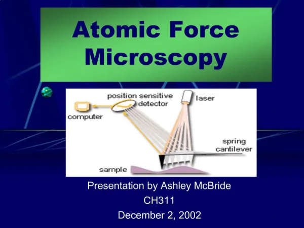
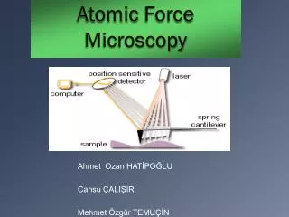
Piezo Drive Photo Detector How AFM Works Camera Laser Beam Cantilever y x z Sample y x
AFM Cantilevers The key piece of any AFM measurement is the cantilever! Materials include: Carbon, Silicon, Silicon Nitride, or Platinum Spring Constants: 0.005 – 60 N/m (application specific selection) Tips have variable characteristics: height, shape, radius, etc. https://www.brukerafmprobes.com/Product.aspx?ProductID=3256 https://www.brukerafmprobes.com/Product.aspx?ProductID=3436
How AFM Works 4 quadrant Photo Detector A B C D Cantilever deflection can be measured in both the x and y direction Vertical Deflection is measured as (A+B) – (C+D) Lateral Deflection is measured as (B+D) – (A+C)
AFM Applications • Imaging • Contact Mode • Tapping Mode • Force Measurements • Colloid Probe AFM (CP-AFM) • Nanoindentation • Single Molecule experiments • Lateral Force Measurements • Custom Applications • Dual cantilever/ correlation force AFM • Lubrication Force AFM • Nanofabrication There are also a variety of specialty techniques used for specific systems.
Contact Mode Imaging • As the name suggests, the cantilever is in direct contact with the sample • Requires a “hard” sample that will not be damaged by the motion or force applied by the tip • Requires a sample that will not create an attractive force with the cantilever or hinder its motion • Typically uses relatively low spring constant cantilevers • Can be preformed in air or liquid
Contact Mode Imaging: How it works Apply a known force (known deflection) to the sample with the cantilever Move the sample (or cantilever) in the x and y planes Measure the change in z-position needed to keep the applied force (deflection) constant Piezo Drive Photo Detector z F Laser Beam Cantilever Sample y x
Contact Mode Imaging: Examples Human Hair Silica sphere http://www.nanoandmore.com/USA/afm-gallery--the-curved-surface-of-a-human-hair-35-micron-scan-taken-with-tap300al-afm-probe-image-900.html
Contact Mode Imaging: Limitations • Limited to “hard” samples • Sample and tip cannot interact • Static • Noise • Limited scan range (~30 μm2) • Limited feature height (~ 1 μm) • Trade off between scan area and image detail
Tapping Mode Imaging: Noncontact Imaging • The cantilever now only “taps” the sample surface • Can be used with “soft” and “hard” sample as this is a nondestructive technique • Requires a sample that will not create an attractive force with the cantilever or hinder its motion • Typically uses relatively high spring constant cantilevers • Can be preformed in air or liquid • Requires cantilevers that can tuned at their resonance frequency
Tapping Mode Imaging: How it works Tune and drive the cantilever at its resonance frequency Define a known change in amplitude to the resonance of the cantilever Move the sample (or cantilever) in the x and y planes Measure the change in z-position needed to keep cantilever amplitude constant Piezo Drive z Sample y x
Tapping Mode Imaging: Examples Nanobubbles on a hydrophobic surface CTAB micelles on graphite http://www.asylumresearch.com/Gallery/Cypher/Cypher4.shtml Nature Methods 6, 792 (2009)
Tapping Mode Imaging: Limitations • Sample and tip cannot interact • Noise • Limited scan range (~30 μm2) • Limited feature height (~ 500 nm) • Trade off between scan area and image detail • Image quality varies based on numerous factors (i.e. drive speed, drive amplitude, and set point) • Limited applications in liquid
Colloid-Probe AFM • Technique developed simultaneously by Ducker et al. and Butt et al. in 1991 • Arose due to issues measuring force interactions with an AFM tip • In this technique, a probe particle is attached to the end of an AFM cantilever, allowing for the forces applied to the particle to be measured • Allows for the measurement of Force versus Separation Distance • Allows for the measurement of a variety of interactions: • Surface interaction forces • Depletion and structural forces • Hydrodynamic interactions Ducker, W.; Senden, T.; Pashley, R. Nature 1991,353, 239. Butt, H.-J. Biophys. J. 1991,60,1438-1444.
Mounting the Probe Particle Probe particles are mounted to AFM cantilever using a variety of glues (i.e. heat setting, epoxy, etc.) Many custom set ups exist for mounting. In some cases the AFM itself is used Computer connected optics X-Y-Z stage Hot Plate
Piezo Drive Photo Detector CP-AFM: How it works Laser Beam Probe particle and cantilever are driven toward and away from the sample at a known rate Deflection vs. drive distance is measured and later converted into force vs. separation Cantilever Scan Rate Sample F
CP-AFM: Processing the Data Region 1 Region 2 Region 3 Region 1: Known as the Constant Compliance region. Defines zero separation and allows for the conversion of deflection voltage to deflection distance Region 2: Region of interaction. Where the forces are. Region of interest Region 3: Zero force region. Used to define zero deflection (i.e. zero force) Deflection/Volts Peizo Drive Distance/nm Contact
CP-AFM: Example Force Curves Interaction of a 5 μm sphere and a flat plate in a solution of micelles Hydrodynamic interaction of a 30 μm sphere with a flat plate
AFM: Custom Application A dual cantilever AFM, also known as a correlation force AFM, is currently being developed in the Department of Chemical Engineering by Dr. Ducker’s group Photo Detector Piezo Drive The interaction of two cantilevers, one driven and one static, is measured across an medium. The cantilever interaction gives information about the medium. Laser Beam Cantilever
AFM: Custom Application As a secondary application of the dual cantilever AFM, a single molecule is stretched between the tips. This allows for the measuring of forces on the molecule
Piezo Drive Photo Detector AFM: Custom Application A lubrication Force AFM is also being developed in Dr. Duckers lab Laser Beam Resonating Cantilever The resonating cantilever is modeled as a simple harmonic oscillator Controlling the separation distance allows for determination of the lubrication properties of the solution h Piezo Drive
Where are the VT AFMs • Department of Chemical Engineering (x3): • Asylum Research Cypher • Asylum Research MFP-3D • Custom Dual Cantilever Set-up • Nano Characterization and Fabrication Laboratory (NCFL): • VeecoBioScope II • Department of Environmental Engineering: • Dr. Vikeland’s Lab • Department of Chemistry • Dr. Esker’s Lab • Department of Physics: • Dr. Tao’s Lab
Thank you Any Questions?