Download
1 / 114
1.15k likes | 1.32k Vues
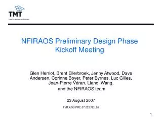
NFIRAOS Preliminary Design Phase Kickoff Meeting. Glen Herriot, Brent Ellerbroek, Jenny Atwood, Dave Andersen, Corinne Boyer, Peter Byrnes, Luc Gilles, Jean-Pierre V é ran, Lianqi Wang, and the NFIRAOS team 23 August 2007 TMT.AOS.PRE.07.023.REL05. Agenda. Welcome and Overview.

E N D
NFIRAOS Preliminary Design Phase Kickoff Meeting Glen Herriot, Brent Ellerbroek, Jenny Atwood, Dave Andersen, Corinne Boyer, Peter Byrnes, Luc Gilles, Jean-Pierre Véran, Lianqi Wang, and the NFIRAOS team 23 August 2007 TMT.AOS.PRE.07.023.REL05
Agenda TMT.AOS.PRE.07.023.REL05
Welcome and Overview Brent Ellerbroek
Adaptive Optics Objectives for TMT • Enable AO-assisted observing modes defined in the SRD • Essential for achieving overall goals of the observatory • Focus on maximizing scientific utility at or shortly following telescope first light • Build upon existing concepts that have been demonstrated to work • Both system architectures and component technologies • Begin by matching actuator densities and control bandwidths of best current systems on 8-10M telescopes • Strive to match Strehl ratios • “D4 scaling” ~100x gain in observing sensitivities • Pursue advanced technologies and system architectures for further capabilities with 2nd generation systems TMT.AOS.PRE.07.023.REL05
TMT Early Light AO Architecture • Narrow Field IR AO System (NFIRAOS) • Mounted on Nasmyth Platform • Feeds 3 science instruments • Cooled to approx. -30 C • Laser Guide Star Facility (LGSF) • Laser enclosure mounted on telescope elevation journal • Launch telescope behind M2 • Conventional optics for beam transport • AO Sequencer (AOSQ) • Science instrument AO functions • IR tip/tilt wavefront sensors • Field derotation at NFIRAOS interface TMT.AOS.PRE.07.023.REL05
TMT AO Group Requirements flowdown Interface definition Contract oversight (mgt/tech) AO analysis and performance modeling AIV planning and participation Other TMT Project Office Departments/Groups Telescope, Systems Engineering, and Site Testing Partners in requirements and interface definition Partners in integrated modeling HIA Support interface and requirement definition Partners in AO analysis/modeling Coordinate with AO component suppliers Develop design Lead factory and site AIV AO component suppliers Detectors (AODP), DMs (CILAS), RTC (TBD) Propose technologies Feedback on req’ts and i/f’s Develop designs Provide components, support AIV NFIRAOS Team Partners and Roles TMT.AOS.PRE.07.023.REL05
Construction Phase Schedule • DDP milestone and activities: • NFIRAOS Preliminary Design work package (8/2007 – 11/2008) • CILAS Tip/Tilt Platform demonstration (4/2007 – 11/2008) • AODP LGS WFS CCD fabrication and test (7/2007 – 5/2008) • RTC algorithm definition (7/2007 – 1/2008) • RTC Conceptual Design study (5/2008 – 10/2008) TMT.AOS.PRE.07.023.REL05
Objectives of Kickoff Meeting • Review NFIRAOS requirements • Convey (extensive) post-CoDR progress to the Project • Performance analysis • Design (overall concept and details) • Outline issues and objectives for the PD phase • Open requirements • Design trades • Performance issues • Component development • Interfaces and ICDs • Present the plan for the PD phase (and beyond) • Obtain feedback on all of the above! TMT.AOS.PRE.07.023.REL05
Review Agenda TMT.AOS.PRE.07.023.REL05
Glen Herriot NFIRAOS Requirements TMT.AOS.PRE.07.023.REL05
NFIRAOS purposes (1) • Observatory Requirement Document specifications: • Facility Laser Guide star AO system feeding three near infrared instruments • 50% sky coverage at galactic pole …with RMS tip/tilt jitter < 0.002” • Wavefront error: 191 nm RMS over 10” Field of View (FoV) • 85% throughput (goal 90%) • NFIRAOS must not increase inter-OH background by more than 15% of sky + telescope background • Science wavelength • 1.0 – 2.5 mm, meeting all requirements simultaneously • 0.8 – 2.5 mm (goal 0.6 to 2.5 mm) with tradeoff in specs. e.g., sky coverage. TMT.AOS.PRE.07.023.REL05
NFIRAOS requirements (2) • Requirements cntd. • 2 arcminute beam fed to instruments • High encircled energy within 160 mas slits on a 2’ FoV for IRMS • Differential photometry at 2% level for 10 minutes integration, for a 30” FOV at 1 mm, with a single standard star in image • Differential astrometric separation to 1% of max(image FWHM, or FWHM/SNR), over 30” FOV for 100 s integration time. Errors should fall as sqrt(t). • High observing efficiency, with a minimum of downtime and night-time calibration • fast target switching < 5 min., (closed shutter time) • fast instrument switching < 10 min., “ “ • Upgradeable to achieve 130 nm rms • Ready for commissioning at first light with low risk, reasonable cost TMT.AOS.PRE.07.023.REL05
Implications for NFIRAOSDesign Concept • Excellent sky coverage • Laser guide star Adaptive Optics (AO) + tip/tilt/focus natural guide star wavefront sensors • MCAO Multi-conjugate AO (multiple Deformable mirrors) with a technical FoV of at least 2 arc minutes for 2 tip/tilt and 1 tip/tilt/focus guidestars • Tip/tilt sensing within instruments, in the infra-red with “sharpened” guidestars • Excellent image quality on a moderate science FoV • Very high order system with multiple laser guidestars and MCAO • Very good throughput and background • Minimum surface count • Systems cooled to approximately -30 Celsius • Wide science wavelength range & specs. for background, sky coverage.. • Beamsplitter changer • Commission system shortly following telescope first light • Use existing and near-term components/concepts when possible • Utilize closed-loop MCAO for wide-field compensation • Utilize Piezostack DM technology • Interactuator spacing of at least 5 mm • mechanically large system • Utilize CW laser guidestar technology • Guidestar elongation bright beacons, advanced algorithms TMT.AOS.PRE.07.023.REL05
Progress Since CoDR -- Summary Glen Herriot
State of play • CoDR design March 2006, with these deltas: • RC telescope • Reduced wind cross section above M1 • Nasmyth platform lowered (NFIRAOS on structure w/ walkways) • Service access for IRIS at HIA & TMT Nasmyth • Substantial LGS WFS redesign - improved cost & risk, ease of Assembly, Integration, Verification and Servicing • Relocated electronics separately • Truth WFS split into MOR TWFS & HOL TWFS • Modeling efforts – many notional error allocations now quantified • Costing done in Sept 06 TMT.AOS.PRE.07.023.REL05
Recent & Near term work • Conceptual design review passed in March 2006 • Work during recent months: • LGS WFS zoom optics redesign to avoid costly off-axis aspheres • FEA model of optical bench for input to Tip Tilt Platform study • Ritchey-Chretien telescope optics – minor rework to science path • Algorithms for Na elongation mitigation • Schedule refining – especially Integration phase with RTC, DMs, IRIS • Early PDR phase work (started in July): • Split Truth WFS into two arms: high-speed and high-order • IR Acquisition camera • Selection of sub-electron read noise detector for NGS-mode WFS • Reduce wind blockage ( refold Truth WFSs path) • Turbulence simulator • TBD? merged with Flat field and Wavelength calibration sources for IRIS and IRMS. • NFIRAOS preliminary design (LGS zoom, source simulator / turbulence generator, operation at -30 C, AIV planning; separate electronics enclosure) TMT.AOS.PRE.07.023.REL05
NFIRAOSScience Optics Path (CoDR) Top Port Off axis paraboloid (OAP) From Telescope Side Port Beamsplitter Instrument Selection Fold DM h=0 km on Tip Tilt platform Focus Preliminary Design: nearly same dimensions as CoDR; Mirrored Left-right layout; slight tweak for Ritchey-Chrétien Telescope DM h=12 km Bottom Port OAP TMT.AOS.PRE.07.023.REL05
2 Truth NGS WFSs 1 60x60 NGS WFS IR acquisition camera Input from telescope OAP OAP 75x75 DM at h=12 km 63x63 DM at h=0 km on tip/tilt platform Output to science instruments and IR T/T/F WFSs IR Visible Laser 6 60x60 LGS WFSs NFIRAOSLatest Optomechanics TMT.AOS.PRE.07.023.REL05
NFIRAOS.ACQ IR Acquisition Camera • Faster acquisition for tip/tilt stars, compared with CCD proposed at CoDR (seconds vs minutes) Science instrument Selection fold mirror can divert output beam to acquisition camera. NFIRAOS.ACQ Infrared Acquisition Camera Top view - IR camera sketched onto CoDR optics design TMT.AOS.PRE.07.023.REL05
MOR Truth & HOL Truth WFSs • Conceptual design of Truth WFS: • Too slow to track sodium layer structure to remove LGS biases • Most centroiding biases are radially symmetric, low order • Split Truth WFS into two: • MOR TWFS • "more truth" wavefront sensor • moderate order radial truth WFS • ~6x6 SH WFS, ~10 Hz. • HOL TWFS (i.e. CoDR TWFS) • "whole truth" wavefront sensor • high order low-speed truth WFS. • 120x120 subapertures, 8x8 pixels each, ~0.1 Hz. Beamsplitters Stage to deploy NGS-mode flat HOL TWFS NGS WFS to run NFIRAOS without Lasers on a bright natural guide star MOR TWFS TMT.AOS.PRE.07.023.REL05
Algorithms for LGS WFS Gain, Offset, and Focus Correction in Real Time LGS Pointing “Centroid” Gain Estimation IR tip-tilt-focus WFS Tilt at 50-500 Hz Focus at 10-100 Hz (TBC) LGS WFS Gains, TBD Hz Focus Lens DM(s) Tip-tilt mirror LGS NGS Visible higher-order WFS Gradient Estimation Offsets, TBD Hz Elect. Focus 10-800 Hz Wavefront Estimation + + TMT.AOS.PRE.07.023.REL05
Progress Since CoDR – Error Budgets and Modeling Luc Gilles, Lianqi Wang, Brent Ellerbroek
AO Performance Modeling Overview Windshake PSD Median Jitter RMS OPD Sky Coverage Simulation • Principal updates since NFIRAOS CoDR • New telescope windshake PSDs • New site turbulence profiles for Armazones, MK13N, Tolonchar • Additional effects now included in LAOS simulations, instead of implementation error budget • Physical optics wavefront sensing with elongated LGS • TMT pupil geometry Guidestar model Turbulence profile P Marechal RMS OPD NGS sharpening IRIS RMS OPD WIRC RMS OPD RSS LAOS PSFs Allocated Implementation & Uncorrected Telescope Errors IRIS Strehls IRMS EEs P Marechal RMS OPD TMT.AOS.PRE.07.023.REL05
Principal Modeling Conclusions • Tip/Tilt jitter and sky coverage have improved considerably with new telescope windshake PSD’s • RMS OPD due to jitter reduced from 85 nm (SRD) to ~ 40/50/60 nm (MK13N/Armazones/Tolanchar) with median windshake • Some margin now exists for noisier detectors and/or stronger windshake • Tip/Tilt-removed Strehls are unchanged to within the accuracy of the modeling and the MASS/DIMM turbulence data • Performance variations between the TMT sites are very modest (~30 nm difference in quadrature) • Performance variation wrt FoV follow the expected trend: • 37 nm (in quadrature) between on-axis and 10’’ average • 46 nm (in quadrature) between 10’’ and 30’’ average TMT.AOS.PRE.07.023.REL05
SRD profile includes a strong layer conjugate to DM12 Median Turbulence Profiles TMT.AOS.PRE.07.023.REL05
Turbulence Parameters Estimates TMT.AOS.PRE.07.023.REL05
Tip/Tilt-Removed IRIS Performancewith Ideal On-Axis NGS Asterism Includes an allocated error budget of 104 nm for implementation errors and uncorrectable telescope errors Estimates are ~25 nm pessimistic (in quadrature) because pupil edge effects are slightly over-estimated with “coarse” pupil sampling of 1/32 m TMT.AOS.PRE.07.023.REL05
Tip/Tilt-Removed WIRC Performancewith Ideal On-Axis NGS Asterism Includes an allocated error budget of 104 nm for implementation errors and uncorrectable telescope errors Estimates are ~25 nm pessimistic (in quadrature) because pupil edge effects are slightly over-estimated with “coarse” pupil sampling of 1/32 m TMT.AOS.PRE.07.023.REL05
IRMS Performancewith Ideal On-Axis NGS Asterism • Excludes 104 nm of implementation and uncorrectable telescope errors - Scales enclosed energy by (0.76, 0.85, 0.92) in (J, H, K) if energy is scattered out of the160 mas slit TMT.AOS.PRE.07.023.REL05
Estimated Tip/Tilt Disturbances Due to Windshake CoDR model Current model at 50, 75, 85, 95 per cent TMT.AOS.PRE.07.023.REL05
Residual Tip/tilt Jitter Due to Windshake Is Significantly Reduced with New PSDs • Improved sky coverage (Lower sampling frequency and dimmer stars for same performance) • Below 80 Hz sampling rate, the double integration scheme providing increased (40 dB per decade) rejection of low temporal frequencies, is turned off to ensure phase margin of control system. Sampling rate at 50% sky coverage is typically ~90 Hz TMT.AOS.PRE.07.023.REL05
Tip/Tilt NGS “Sharpening” with Measured Site Turbulence Profiles TMT.AOS.PRE.07.023.REL05
RMS Tip/Tilt Jitter at 50% Sky Coverage Has Significantly Improved Quadrant detectors with 10 electrons read noise Prior estimate with the CoDR windshake profile was 85 nm RMS TMT.AOS.PRE.07.023.REL05
Tip-Tilt Included RMS Wavefront Errors for IRIS and WIRC (nm) Quadrant detectors with 10 electrons detector read noise 104 nm RMS implementation errors TMT.AOS.PRE.07.023.REL05
Some Margin Now Exists for Increased IR WFS Detector Read Noise TMT.AOS.PRE.07.023.REL05
Sky Coverage in NGS AO Mode • Study prepared for TMT SAC in response to a suggestion from the TMT EAP • Results better than might be expected • Low telescope windshake • WFS detectors with sub-electron read noise • Order 60x60 AO compensation is preferred to a lower-order AO system for the same reasons • One per cent sky coverage is achieved at Strehl ratios of (about) 0.10, 0.25, 0.45 in J, H, and K bands • Or 0.15, 0.30, 0.55 with 25% seeing • Implementation error sources included TMT.AOS.PRE.07.023.REL05
Performance Metrics, Parameter Assumptions, and Design Options • Performance metrics • RMS OPD, Strehl ratio, ensquared energy in a 50 mas pixel • NGS model • Bahcall-Soniera model at the galactic pole • Decomposed into spectral classes by Doug Simons (Ellerbroek/Tyler PASP 1997) • Input wavefront disturbances • Armazones 50% and 25% turbulence profiles • 101 nm RMS uncorrectable implementation errors (no windshake) • AO control system options • Order 30x30 or 60x60 wavefront compensation • 0.25 to 100 Hz -3dB control bandwidth • Minimum variance reconstructor with Fourier domain modal truncation • Radiometric and WFS noise modeling • 56% throughput to NGS WFS within 0.630--0.945 mm passband • E2V LLL or MIT/LL AODP WFS detector with 2x2 pixels/subaperture TMT.AOS.PRE.07.023.REL05
NGS Limiting Magnitude is Dramatically (!) Improved with Low Read Noise Detectors • On-Axis, class F guidestar • Optimized control bandwidths • No implementation error sources • Order 60x60 compensation • E2V LLL array with 0.25 (black) or 5 (red—included as a sanity check) noise electrons per pixel per read TMT.AOS.PRE.07.023.REL05
Sky Coverage • Order 60x60 Compensation, E2V LLL detector TMT.AOS.PRE.07.023.REL05
How Should More Detailed Requirements for NGS AO Be Specified? • Performance vs. NGS magnitude? • Performance vs. sky coverage? • For what atmospheric conditions? • For what performance metrics? • At what science wavelengths? • Specialized or more specific requirements? • PSF reconstruction • PSF stability • High contrast imaging applications • Etc…. TMT.AOS.PRE.07.023.REL05
Optics & Mechanics(switch to separate presentation files) Jenny Atwood, Peter Byrnes
NFIRAOS AO Architecture, AO Sequencer, RTC Corinne Boyer
AO Architecture Requirements • Near diffraction limited wavefront quality in the near IR • High sky coverage • Feed up to 3 instruments, including the early light instruments IRIS and IRMS. • These requirements are met using an LGS MCAO architecture composed of 3 main systems: • Facility AO system NFIRAOS • Laser Guide Star Facility (LGSF) • AO Sequencer TMT.AOS.PRE.07.023.REL05
Instruments and AO systems pass science data to the Science Data System: • handling tools/libraries • Visualization tools • Quality assessment • Local and remote storages • Data processing Control of NFIRAOS/IRIS The TCS provides: • the pointing/tracking kernel and libraries for ADC, WFS positioning, field rotation, WCS • the sequencer that sequences the telescope systems during an observation. OCS provides: • the observer graphical user interface, • the sequencer that sequences the telescope systems, the AO systems and the instrument during an observation The AO Sequencer and Instrument Sequencer sequence their respective sub-systems during an observation. IRIS NFIRAOS TMT.AOS.PRE.07.023.REL05
AO Sequencer Top Level Requirements • Sequence and coordinate the AO systems (LGSF, NFIRAOS) and instrument AO components (Tip Tilt Focus WFS’s, etc.) • Three categories of sequences: • AO calibration: • Day and night time calibration of LGSF, NFIRAOS, and instrument Tip Tilt Focus WFSs • AO configuration: • LGSF configuration: projecting the required asterism • NFIRAOS configuration: • Selecting the AO mode and instrument port • Positioning the WFS mechanisms • Configuring the NFIRAOS Real Time Controller (RTC). • IR TTF WFS configuration: positioning the WFS mechanisms • AO operations: • Acquiring the guidestars and closing the loops • Managing the closed loop in NGS, LGS, or seeing limited mode TMT.AOS.PRE.07.023.REL05
NGS IRIS acquisition sequence NGS IRIS, IFU mode Tip/Tilt sensing using one IR TT(F) WFS (less anisoplanatic error, reduced measurement noise, instrument flexure compensation) Baseline acquisition scenario using the acquisition camera Timing: 228 s (~3.8 minutes)* *assuming 3 minutes for telescope setup TMT.AOS.PRE.07.023.REL05
LGS IRIS acquisition sequences LGS IRIS, IFU mode Baseline acquisition scenario using the acquisition camera: 289 s (~4.8 minutes)* Alternative scenarios: - Blind acquisition scenario: 219 s (~3.6 minutes)* • Spiral acquisition scenario: 224 s (~3.7 minutes after 2 steps)* *assuming 3 minutes for telescope setup TMT.AOS.PRE.07.023.REL05
IRMS seeing limited acquisition sequence Seeing limited IRMS mode Tip/Tilt sensing using one IR TT(F) WFS Higher order modes using 6x6 TWFS Blind acquisition TMT.AOS.PRE.07.023.REL05
AO Sequencer Top Level Requirements, Continued • Offload DM corrections for persistent, low-order wavefront aberrations to M1 and M2 • Providing AO reconstruction parameters to the RTC • Initial parameters for WFS gradient estimation • Matrices for wavefront reconstruction updated at a slow rate • Post-processing science PSFs using the wavefront structure functions computed in real time by the RTC • Extensibility and maintainability TMT.AOS.PRE.07.023.REL05
AO Sequencer Block Diagram TMT.AOS.PRE.07.023.REL05