Download
1 / 136
1.36k likes | 1.38k Vues
Learn the fundamental concepts of orthographic projection, from creating standard views to mastering line types in exercises. Explore engineering graphics overview and key points for a comprehensive understanding.

E N D
Chapter 1Orthographic Projection Basic Topics Advanced Topics Exercises
Ortho. Projection: Basic Topics 1.1) Engineering Graphics Overview Summary 1.2) Orthographic Projection 1.3) The Glass Box Method 1.4) The Standard Views 1.5) Lines Used in an Orthographic Projection 1.6) Rules for Line Creation and Use 1.7) Creating an Orthographic Projection
Ortho. Proj.: Advanced Topics 1.8) Auxiliary Views
Ortho. Projection: Exercises Exercise 1-1: Principle views Exercise 1-2: Line types Exercise 1-3: Line use in an orthographic projection Exercise 1-4: Missing lines 1 Exercise 1-5: Missing lines 2 Exercise 1-8: Drawing an orthographic projection 1 Exercise 1-9: Drawing an orthographic projection 2
Ortho. Projection: Exercises Exercise 1-12: Auxiliary views
Engineering Graphics 1.1) Introduction to Engineering Graphics
Engineering Graphics • What is Engineering Graphics? • What is an Engineering Drawing? A set of rules and guidelines that help you create an Engineering Drawing. A drawing that communicates an idea or design.
Engineering Graphics • Examples of Engineering Drawings • Mechanical Engineers • Detailed drawing of a part that needs to be machined. • Electrical Engineers • A circuit schematic. • Circuit board layout. • Civil Engineers • Plans for a bridge. • Road layout.
Orthographic Projection Summary
Summary • What will we learn in Chapter 1? • How to create an orthographic projection. • Key points • An orthographic projection is a 2-D representation of a 3-D object.
Orthographic Projection 1.2) Orthographic Projection Introduction
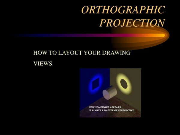
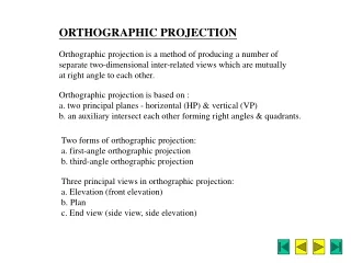
Introduction • Orthographic projection = 2-D representation of a 3-D object.
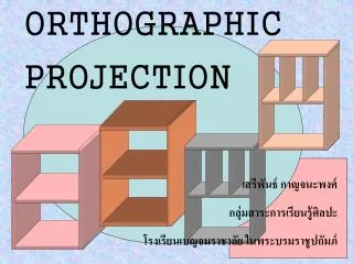
Introduction • An orthographic projection represents different sides of an object.
The Six Principal Views • The 6 principal views are created by looking at the object, straight on, in the directions indicated.
Orthographic Projection 1.3) The Glass Box Method
The Glass Box Method • How do we create the 6 principal views? The Glass Box Method
Glass Box Method • The object is placed in a glass box. • The sides of the box represent the 6 principal planes.
Glass Box Method • The image of the object is projected on the sides of the box.
Glass Box Method • Things to notice! • The projection planes. • The projectors. • How surfaces A and B are projected.
Glass Box Method • The box is unfolded creating the 6 principal views.
Exercise 1-1 Principal Views
Exercise 1-1 • Label the 5 remaining principal views with the appropriate view name.
Name each view. Top
Name each view. Top Right Side
Name each view. Top Rear Right Side
Name each view. Top Left Side Rear Right Side
Name each view. Top Rear Left Side Right Side Bottom
What are the differences between the Right Side and Left Side views? Top Rear Left Side Right Side They are mirror images with one different line type. Bottom
What are the differences between the Top and Bottom, and Front and Rear views? Top Rear Left Side Right Side They are mirror images with different line types. Bottom
Which view(s) have the least amount of hidden or dashed lines? Front and top views. Top Rear Left Side Right Side Bottom
Orthographic Projection 1.4) The Standard Views
Standard Views • When constructing an orthographic projection, we need to include enough views to completely describe the true shape of the part. • Complex part = more views • Simple part = less views
Standard Views • The standard views used in an orthographic projection are; • Front view • Top view • Right side view • The remaining 3 views usually don’t add any new information.
Standard Views • How many views do we need to completely describe a block?
Standard Views • How many views do we need to completely describe a block? 2 views. The 3rd view duplicates information.
Standard Views • How many views do we need to completely describe a sphere? 1 view. A sphere has only one dimension. Its diameter.
Front View • The front view shows the most features or characteristics of the object. • It usually contains the least amount of hidden lines. • The front view is chosen first and the other views are based on the orientation of the front view.
View Alignment • The top and front views are aligned vertically and share the same width dimension. • The front and right side views are aligned horizontally and share the same height dimension.
Orthographic Projection 1.5) Lines Types Used in an Orthographic Projection
Line Type and Weight • Line type and line weight provide valuable information to the print reader. • For example, line type and weight can answer the following questions. • Is the feature visible or hidden from view? • Is the line part of the object or part of a dimension? • Is the line indicating symmetry?
Line Type and Weight • There are four commonly used line types; • continuous • hidden • center • phantom
Line Type and Weight • Some lines are more important than others. Importance is indicated by line weight or thickness. • The thicker the line, the more important it is.
Line Types • Visible lines: • Visible lines represent visible edges and boundaries. • Continuous and thick (0.5 - 0.6 mm). • Hidden lines: • Hidden lines represent edges and boundaries that cannot be seen. • Dashed and medium thick (0.35 - 0.45 mm).
Line Types • Center lines: • Represent axes of symmetry. • Long dash – short dash and thin (0.3 mm).
Line Types • Phantom line: • Phantom lines are used to indicate imaginary features. • alternate positions of moving parts • adjacent positions of related parts • The line type is long dash – short dash – short dash and the line weight is usually thin (0.3 mm).
Line Types • Dimension and Extension lines: • Dimension and extension lines are used to show the size of an object. • In general, a dimension line is placed between two extension lines and is terminated by arrowheads, which indicates the direction and extent of the dimension. • The line type is continuous and the line weight is thin (0.3 mm).
Line Types • Cutting Plane line: • Cutting plane lines are used to show where an imaginary cut has been made through the object in order to view interior features. • The line type is phantom and the line weight is very thick (0.6 to 0.8 mm). • Arrows are placed at both ends of the cutting plane line to indicate the direction of sight.
Line Types • Section line: • Section lines are used to show areas that have been cut by the cutting plane. • Section lines are grouped in parallel line patterns and usually drawn at a 45 angle. • The line type is usually continuous and the line weight is thin (0.3 mm).
Line Types • Break line: • Break lines are used to show imaginary breaks in objects. • A break line is usually made up of a series of connecting arcs. • The line type is continuous and the line weight is usually thick (0.5 – 0.6 mm).