Download
1 / 17
170 likes | 421 Vues
An experiment in computed tomography. Elliot Mylott (emylott@pdx.edu) Ryan Klepetka Justin Dunlap Ralf Widenhorn (ralfw@pdx.edu). Buzug, Thorsten M. Computed Tomography: From Photon Statistics to Modern Cone-Beam CT. Physics Department Portland State University, Portland, OR. Objectives.

E N D
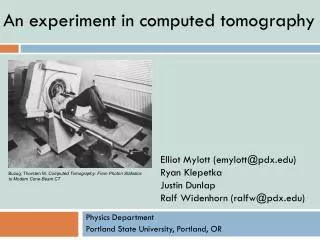
An experiment in computed tomography Elliot Mylott (emylott@pdx.edu) Ryan Klepetka Justin Dunlap Ralf Widenhorn (ralfw@pdx.edu) Buzug, Thorsten M. Computed Tomography: From Photon Statistics to Modern Cone-Beam CT Physics Department Portland State University, Portland, OR
Objectives • To design a lab that • Introduces students to CT • Utilizes light instead of X-rays • Requires little setup • Fast data collection and analysis • Reinforces concepts of light/matter interaction • Can highlight CT specific issues
An Example of X-rays and Projections for Students X-ray film Projections X-ray tube
CT and Back Projection • X-ray source rotates around an object accumulating projection data • Projection data reflect the attenuation of the X-ray by the object • Projection data is spread back onto a reconstructed image • Multiple scans from different angles result in an image of the original object Projection Data X-ray Source Projection Data Projection Data 1 1 1 1 1 1 1 1 1 1 1 Backprojectionimage
An Example of Back Projection for Students Three light sources on a cylinder Shadows (projections) converge at the cylinder
Scanner Generations 1st Generation 2nd Generation 3rd Generation 4th Generation • Translation & Rotation • Pencil Beam • Single Detector • Translation & Rotation • Small Fan Beam • Small Detector Array • Rotation Only • Large Fan Beam • Large Detector Array • Rotation Only • Large Fan Beam • Stationary Detector Array • Rotation Only • Pencil Beam (Simulated Fan Beam) • Single Detector (Simulated Large Detector Array)
Hidden Objects http://amasci.com/amateur/irgogg2.html
Comparison to X-ray CT Scanners Rotate X-ray Source Rotate Scanned Area
Comparison to X-ray CT Scanners Attenuation 0 1 Analog Projection Data Digital Projection Data Photogate Scan X-ray tube
Scanner Geometry • Variables • FCD – distance between the center of the grid and the rotary motion sensor • θ - The angle between the rotary motion sensor and the x-axis • φ – The angle between the focal length line and the scanning line • Output • Equation for the scanning line (y=mx+b) Rotational Axis y IR Source IR Detector Scanning line Focus-Center Distance (FCD) x
LabVIEW • Displays data in real time • No programming experience needed • Can be adjusted for different computer speeds • Will be available as an .exe file
Creating an Image Original Positions Final Reconstruction θ=360 θ=180
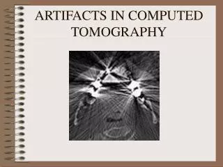
CT Concepts - Artifacts Back projection results in additional, unwanted data.
CT Concepts -Windowing Change in Gray Scale Value