Download
1 / 36
360 likes | 748 Vues
Learn about the operational heart of audio mixing - the audio mixer. Understand its functions, routing capabilities, and built-in processors like equalizers and compressors. Gain insights into sound mixer channels, input levels, and audio processors.

E N D
AUDIO MIXER AND AUDIO PROCESSING BY Engr. John Madah
OBJECTIVES At the end of the training, participants are expected to understand the audio Mixer audio Processing
THE AUDIO MIXERS A mixer or Mixing Desk, or Mixing console or Software Mixer is the operational heart of the Mixing process. A mixer has a multitude of inputs, each is fed either by a microphone, Line input or a track from a multi-track recorder. A mixer would normally have two or more outputs in the case of two- channel stereo mixing or eight in the case of surround sound.
What does a Mixer do? • No matter how sophisticated or expensive, all mixers carry out the same basic function — to blend and control the volume of a number of input signals, add effects and processing where required and route the resulting mix to the appropriate destination, which could be power amplifiers, the tracks of a recording device — or both. • A mixer is the nerve centre of these sources, and therefore the most vital part of your audio system.
Audio mixers offers three main functionalities: • MIXING: Summing signals together which is normally done by a dedicated summing amplifier or In the case of digital, by a simple algorithm. • ROUTING: Allows the routing of source signals to internal buses (e.g. Auxiliary bus, Groups, Monitor e.t.c), or external processing units and effects (Compressors, Limiters, Noise gates, Effects generators, Feedback destroyers).
PROCESSING: Many mixers also offer on board processors, like Equalizers and Compressors. • PROCESSORS: These devices are normally connected in series to the signal path so the input signal is replaced with the processed signal e.g. Equalizers’ • EFFECTS: While an effect can be connected as any unit that affects the signal, the term is mostly used to describe units that are connected in parallel to the signal path and therefore they add to the existing sounds, but do not replace them. • Example would include Reverbs and delays.
Reverbs: Used to simulate boundary reflections created in a real room, adding a sense of “Space and depth” to otherwise “dry” recordings • Delays:Most commonly used to add distinct echoes as a creative effect. SOUND MIXER CHANNELS • The first point of each channel’s pathway is the input socket, where the sound source plug into the mixer. Available sockets includes : XLR (canon), 6.5mm Jack and RCA (Phono) plugs. • XLR: Microphones and some Audio devices. It accept balance and unbalance signals. • 6.5mm Jack: Musical instruments such as electric Guitars, as well as various audio devices. Mono Jacks are unbalance. Stereo Jacks can either be balance stereo or balance mono. • RCA: Musical devices such as disk players, record players, Set top boxes, Receivers, etc.
Controls available on a typical Audio Mixer • Input Gain Attenuator: Control level of signal as it enter channel. It uses a potentiometer. There may be a switch or pad which will increase or decrease the level by a set amount (Mic/Line switch). • Phantom Power: Turns phantom power on or off. • Equalizers: Most mixers have at least two EQ controls – High and Low frequencies control. Good mixer have at more advance in particular, parametric EQ. • Auxiliary channels outputs: used to send a copy of the channel signal somewhere else to provide separate monitor feeds or to add effects. • Pan & assignment: i.e, Pan left or Right. • Channel On/Off: Turns the entire channel on/off.
Slider: Control the level of the channel signal as it leaves the channel to the next stage (Sub group or Master mix). • Sub Group: Provide a way to sub-mix a groups of channels before they are sent to the main output Mix. • Master slider: Final mix fader • Phasing Knob: Used to change the Phase of signal. INPUT LEVELS • The level of an audio signal refers to the voltage level of the signal. • Signals can be divided into three categories: • Mic-level (Low), Line-Level (a bit higher) and Loudspeaker level (very high). • Microphones produces a Mic-level signal where as most audio devices such as disc players, wireless microphones produce a line-level signal. • Loudspeaker level signals are produced by Power amplifiers and are only appropriate for plugging into a loudspeaker. (Note: Never plug a loud speaker signal into the audio mixer input).
AUDIO PROCESSORS • INCLUDES: COMPRESSORS/EXPANDERS, LIMITERS AND GATES. EQUALIZERS/ FILTERS
COMPRESSORS/EXPANDERS, LIMITERS AND GATES. • Dynamic Range: • Before we look at compressors and limiters we must understand the term Dynamic Range. The Dynamic Range of a sound is the range between the quietest section and it's loudest section or in the case of a recorder the range between the noise floor and the point of distortion.
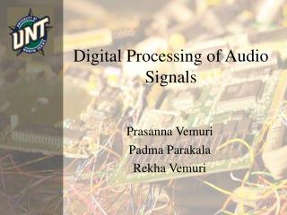
The meters above show a dynamic range of 72db. On a home cassette recorder the quiet section in this track would be below the noise of the tape recorder and all you would hear through the quiet passage would be tape hiss. The distance from the loudest section to the point of distortion is called the Headroom. If distortion is reached at +6db then we currently have a 4db headroom. To reduce the dynamic range you could ride the whole track with a fader and turn it up when it's too low and pull it back when too high or your can use a compressor. • A Compressor can change the input signal to output signal ratio. They manipulate the dynamic content of signals.
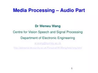
Fig. A In Fig. A above unity gain means that what you put in you get out. In the 2:1 ratio example When the signal is above the threshold the signal output is reduced in a ratio of 2db in will give 1db out when the compression ratio is set at 2:1,
so you have saved 1 db off the top of your dynamic range and you can turn it all up by 1 db without effecting the headroom. • In a more severe case like the 20:1, which is more commonly called limiting, for a 20 db rise in signal only 1 db comes out. • The compressor and limiter can be used together in one unit where the compressor works in the 2 - 15:1 range whilst the limiter stops the extreme transient peaks in the signal in the 15 - 20:1 ratios which is why it is often called a Peak Limiter.
In the above graph the threshold of the limiter has been raised so that the main program material will be compressed above the threshold of compression at 2:1 and above the limiting threshold it will be 20:1. A compressor is a gain reduction device, therefore all compressors have a make up gain control so that if you are using 3db of gain reduction you can turn the output by that amount and still retain the same headroom
In the diagram above the transition from unity gain to compression at the threshold of compression/limiting is gradual instead of a straight line. This is called a Soft Knee threshold and is much smoother. • The Meter on a compressor can usually be switched to read either the input level, output level or the amount of gain reduction. It is advisable to check that the input level is correct before you start adjusting the threshold and setting the compression ratio etc.
The attack time determines how quickly the compressor reacts to signals above the threshold. • Signals have short sharp peaks called Transients that can easily trigger a compressor to act. • The attack time determines how long the peak should be above the threshold before compression takes place. These short transients are important in the clarity of a sound but don't affect the loudness of the sound. The aim of compression is to make the instrument sound louder, to squeeze the dynamic range, therefore you may wish to lengthen the attack time and let the transients through (to be dealt with by a limiter if necessary) and the compressor will then be working on sustained levels above the threshold. • Therelease time determines how quickly the compressor lets go, or restores normal gain. If the release is too fast for the amount of gain reduction applied then the return to normal gain over and over as the signal moves above and below the threshold can cause what is known as pumping because the gain structure is changing rapidly. It is advisable to ask the player to play sustained notes and set the release so the change of gain is smooth. Instruments that have long sustaining notes like bass guitars should tend to use a slower release times than sharp percussive instruments like percussion. Most of the new generation compressors now have an Auto button that leaves it to the compressor to work it out, and they usually do it fine
The left section is the Noise Gate section. It has controls for the threshold at which the gate opens the release time variable and a switchable fast/slow attack control. • The centre section is the compression section with the standard controls over threshold, ratio, attack and release. • The Peak/RMS switch determines how the compressor will track the signal i.e. its peak content or its RMS content. • TheAutobutton is often an option where the compressor works out the attack and release times itself by analysing the program material.
Thehard/soft switch determines the Knee setting. The meter can read input or output levels plus it can read the amount of gain reduction. Finally there is the makeup gain control (Often just labelled output level) • Thelink button is there if there are two compressors in the unit . Stereo Compressors have a link facility that makes one of the two compressors a master. (Usually the left compressor). • All the controls on the master effect the slave compressor, so they both operate together. If the compressors weren't linked any strong signal on the right would be gain reduced and the stereo image would move because centre panned instruments would vary in their left to right balance so when compressing a stereo signal make sure the compressors are linked. • Similarly take a look at this image of a Computer program Compressor by Waves. All the controls are there.
Expanders • The expander is a compressor in reverse. There are two types of expander. In some, signals above the threshold remain at unity gain whereas signals below the threshold are reduced in gain, whereas in others the signal above the threshold also has the gain increased. Therefore you can use an expander as a noise reduction unit. Set the threshold to be just below the level of the player when playing. When the player stops the signal will fall below this threshold and the signal is reduced in gain thus reducing the noise or
Limiters • A limiter is just a severe compressor where the compression ratios are high. On some units like the DBX 160 and the Aleisis compressors an additional Peak limiter control with a LED that flashes is supplied, but units like the Aphex Dominator are pure limiters and are very sophisticated in how they attack and control peaks and you can get some pretty hot "brick wall" mixes through them. • Noise Gates • Noise gates are units that let a signal pass if it's above a certain level and shut it down if it's below that threshold.
THE END ???
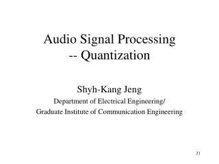
Audio connectors Female XLR connectors Male XLR connectors Audio connectors Shield Hot + Cold - Balance XLR-XLR connection Balance XLR- Jack