Download
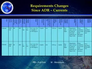
1 / 25
250 likes | 263 Vues
Understand how highly charged plasma from the sun creates GICs affecting various systems. Learn about major geomagnetic storms, necessary data for calculations, and proposed modeling schedule.

E N D
Data Requirements For Calculating Geomagnetically Induced CurrentsPGDTF Meeting March 21, 2016 Michael Juricek PGDTF Chairman
Space Storm Michael Juricek – 3/21/2016 PGDTF Meeting
What are Geomagnetically Induced Currents (GIC)? • Highly charged cloud of plasma is ejected from the sun – coronal mass ejection (CME) • Some of the plasma enters the earth’s ionosphere • The electro-magnetic interaction with earth’s magnetic field results in time varying electrojets of current in the ionosphere producing the auroras • The fluctuating electrojet currents induce voltages and currents in the earth’s crust and electric transmission systems Michael Juricek – 3/21/2016 PGDTF Meeting
What are Geomagnetically Induced Currents (GIC)? • Induced voltage in the earth causes GIC in the lines • Currents are “zero sequence” “quasi dc” currents • Not displaced by 120 degrees like 60 Hz load currents • To flow the currents need a path to circulate • Path is typically provided by transformers and shunt grounding connections • TSPs and Resource Entities are affected Michael Juricek – 3/21/2016 PGDTF Meeting
Major Geomagnetic Storms in Past • 1859 Carrington Storm • Damaged telegraph systems • Some operated without damaged batteries • Sparks shocked operators and caused fires • Lasted for 12 days • 1921 Storm • Less severe than 1859, but still damaged telegraph systems • March 13, 1989 Storm • 1/10th strength of 1921 storm • Damaged transformers in USA and other countries • Blackout in Canada (Hydro Quebec/Hydro One) in 92 seconds • Auroral zone expanded to Gulf Coast Michael Juricek – 3/21/2016 PGDTF Meeting
GIC data files for PSS/E Model Michael Juricek – 3/21/2016 PGDTF Meeting
GIC Data • Required data from TSPs and Resource Entities • Geographic location of substations (longitude and latitude) • Grounding resistance data for substations • Bus substation numbers (allows all substation components in one location to be grouped together into one substation) • DC resistance of transformer windings • Winding grounding dc resistance • Identification of GIC blocking device in the grounding connection • Transformer vector group • Bus Shunts • DC resistance of transmission lines • Number of cores in transformer • K Factor Michael Juricek – 3/21/2016 PGDTF Meeting
Substation Data I, NAME, UNIT, LATITUDE, LONGITUDE, RG, EARTHMDL Where: Michael Juricek – 3/21/2016 PGDTF Meeting
Bus Substation Data BUSNUM, SUBNUM Where: Michael Juricek – 3/21/2016 PGDTF Meeting
Bus Substation Data Michael Juricek – 3/21/2016 PGDTF Meeting
Bus Substation Data Michael Juricek – 3/21/2016 PGDTF Meeting
Substation Data Example • Source: Siemens PTI 2012 Michael Juricek - 3/21/2016 PGDTF Meeting
Bus Substation Data • Source: Siemens PTI 2012 Michael Juricek - 3/21/2016 PGDTF Meeting
Transformer Data I, J, K, CKT, WRI, WRJ, WRK, GICBDI, GICBGJ, GICBDK, VECGRP, CORE, KFACTOR, GRDWRI, GRDWRJ, GRDWRK, TMODEL Where: Michael Juricek – 3/21/2016 PGDTF Meeting
Bus Fixed Shunt Data I, ID, R, RG Where: Michael Juricek – 3/21/2016 PGDTF Meeting
Transformer MVAR Scaling Factors • Source: Siemens PTI 2012 Michael Juricek - 3/21/2016 PGDTF Meeting
Transformer Data Example • Source: Siemens PTI 2012 Michael Juricek - 3/21/2016 PGDTF Meeting
Branch Data I, J, CKT, RBRN, INDVP, INDVQ Where: Michael Juricek – 3/21/2016 PGDTF Meeting
User Earth Model Data NAME, BETAFTR, DESC, RESISTIVITY1, THICKNESS1, RESISTIVITYn, THICKNESSn Where: Michael Juricek – 3/21/2016 PGDTF Meeting
Default Data Versus Actual Data • Software developer used actual data to develop default data which is assumed conservative data • Default data may produce higher GICs and reactive loading than actual data • Experienced TSPs highly recommend actual data • Consultants highly recommend actual data • PGDTF has decided to use actual data, where possible Michael Juricek – 3/21/2016 PGDTF Meeting
Proposed Modeling Schedule • June 1 – TSPs and REs start providing data to ERCOT • November 1 – All data must be submitted to ERCOT Michael Juricek – 3/21/2016 PGDTF Meeting
Questions and Answers Michael Juricek – 3/21/2016 PGDTF Meeting
Appendix Michael Juricek - 3/21/2016 PGDTF Meeting
FERC March 1, 2016 Technical Conference • FERC commissioners and staff participated • Benchmark GMD event and geomagnetic fields • Earth conductivity model • Harmonics and vibrational effects during benchmark GMD events • Selection of 75 Ampere threshold for thermal assessments • Modeling capabilities regarding transformer thermal assessments • Non-uniform geoelectric fields • Corrective action plans • Current state of monitoring • Potential for additional monitoring • Improvement in modeling and analysis tools Michael Juricek – 3/21/2016 PGDTF Meeting
FERC March 1, 2016 Technical Conference continued • Comments • Adopt standard as proposed and revise as better data and analysis techniques indicate • Make benchmark event more severe in standard • Lower GIC threshold for transformer thermal assessment such as 15 Amperes in standard • Use actual GIC data to validate benchmark event • Increase monitoring of GIC geomagnetic fields and geoelectric fields • Improve earth models • Provide real-time GIC readings to control rooms • Study multiple GMD scenarios to determine the system’s strength • Share GIC measurements with public Michael Juricek – 3/21/2016 PGDTF Meeting