Download

1 / 1
20 likes | 155 Vues
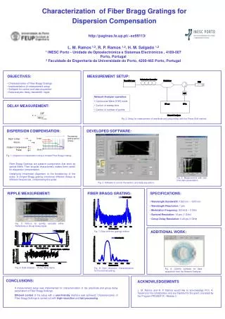
GPIB. Vectra PC and Monitor. Controller PC running instrument control software. Tunable laser. GPIB. CFBG. HP 8509B Polarization State Analyzer. S 3. RCP. LVP. L -45. S0’ m00 m01 m02 m03 S0 S1’ = m10 m11 m12 m13 S1

E N D
GPIB Vectra PC and Monitor Controller PC running instrument control software Tunable laser GPIB CFBG HP 8509B Polarization State Analyzer S3 RCP LVP L -45 S0’ m00 m01 m02 m03 S0 S1’ = m10 m11 m12 m13 S1 S2’ m20 m21 m22 m23 S2 S3’ m30 m31 m32 m33 S3 LHP L +45 S2 S1 LCP Characterization of second-order PMD in chirped fiber Bragg gratings C. Miscisin, R. Saperstein, K. Tetz, and Y. Fainman Background: Experimental Set-Up: • Chirped Fiber Bragg gratings (CFBGs) are useful for Fiber Optic Communications and Optical Signal Processing • CFBGs can be used for dispersion compensation in long haul fiber optic transmission systems • Each wavelength is reflected at a different location along the fiber canceling pulse spread caused by chromatic dispersion • However, CFBGs suffer from severe 2nd order polarization mode dispersion (PMD) • Each spectral component of light receives an independent polarization rotation • If this 2nd order PMD can be characterized, then it can be compensated. Stokes Polarization Parameters Poincaré Sphere Mueller Matrix Formalism • In 1852, Sir George Gabriel Stokes discovered that the polarization behavior of light could be represented in terms of real observables, he developed a mathematical statement that could represent fully, partially, and even un-polarized light. • The Stokes polarization parameters can be obtained by direct measurement of the time averaged intensity of a lightwave that has passed through a retarder and a polarizer in sequence. • Around 1890 Henri Poincaré discovered that the polarization ellipse could be represented on a complex plane and that this plane could be projected onto a sphere. • Six basis polarization states have Stokes vectors which define the 3D axes of the Poincaré sphere . • In the early 1940’s Hans Mueller became the first person to describe polarizing components in terms of matrices. • To derive a Mueller matrix for a polarization altering device, for a single wavelength of light, we have four equations and sixteen unknowns. • Using four of the six basis polarization states the calculation of a Mueller matrix is simplified. I(0,0) + I(90,0) = I(0, 0) - I(90,0) 2I(45,0) – I(0,0) – I(90,0) 2I(45,90) – I(0,0) – I(90,0) S0 Eox2 + Eoy2 S1 = Io Eox2 - Eoy2 S2 2EoxEoycosδ S3 2EoxEoysinδ total intensity amount of LHP or LVP Incident Stokes vector Amount of RCP or LCP amount of linear L+45 or L-45 (retardation, orientation of polarizer) Experiment: Resultant Stokes vector Mueller matrix describing a polarization altering device • A Mueller matrix is derived for each wavelength • Polarization measurements were taken every ¼ wavelength from 1535nm to 1565nm • Polarization states resulting from the input of each basis polarization for the specified range of wavelengths are displayed below • Stokes polarization parameters and their locations on the Poincaré sphere Linear +45o Polarized Light (L45) Linear Horizontally Polarized Light (LHP) Linear Vertically Polarized Light (LVP) Right Circularly Polarized Light (RCP)