ME 442 Senior Project
320 likes | 442 Vues
ME 442 Senior Project. Autonomous Hovercraft – Class of 2008-2009. Project Summary 4/30/09. Joseph Cochrane, Patrick Dickey, Aldo Glean, James McMahon, Omar Monterrubio, Kalin Petersen, Jason Shao. Post-Conflict Mine Fields.

ME 442 Senior Project
E N D
Presentation Transcript
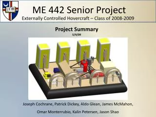
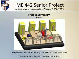
ME 442 Senior Project Autonomous Hovercraft – Class of 2008-2009 Project Summary 4/30/09 Joseph Cochrane, Patrick Dickey, Aldo Glean, James McMahon, Omar Monterrubio, Kalin Petersen, Jason Shao
Post-Conflict Mine Fields Unexploded landmines from previous military conflicts are still a prevalent issue in civilian 3rd world areas Estimated 1 million unexploded landmines left over from a skirmish between Israel and Lebanon in 2006 Cambodia has one amputee for every 290 people - one of the highest ratios in the world.
Landmines Anti-personnel landmines are generally small and designed to maim, not kill Most anti-personnel landmines are detonated when about 5psi of contact pressure is applied to a triggering mechanism on the device Can be triggered via a person stepping on device, driving over device, increased pressure or vibration
Why a Hovercraft? Is a vehicle that uses an engine to drive a large fan inside a structure, which creates an air cushion within a fabric skirt Provides lift force to counteract the weight of the craft while applying very little pressure to the surface beneath, ~0.1psi Capable of traveling over solid, marshy and wet terrains, making it adaptable to the various rural environments
Our Concept We intend to develop a means for civilian land-mine location that is inexpensive and easily reparable Our intention is to design the platform for carrying detection technology, not develop the technology itself
Presentation Outline ME 441 summary Ground Penetrating Radar (GPR) Lift engine mount Lift engine shroud Pressure testing Pulley attachment Propulsion and electronics power systems Thruster housing mesh and design testing Component layout and balance analysis Controls
ME 441 Summary • A larger hullwas designed to accommodate the Ground Penetrating Radar antennae and the various system components • Air flow and lift calculations performed • New hull and skirt constructed and tested • Lift engine acquired • Lift fan selected and acquired • Thruster housing design modified and four units constructed
Ground Penetrating Radar • Penetradar GPR system outfitted with IRIS processing software provided by U.S. Army Night Vision Directorate • Test designed to observe its detection capabilities
Navigation System • Acquired differential GPS components (~3cm resolution) from U.S. Army Night Vision Directorate • Will allow position and direction of the craft to be monitored from a remote location
Pressure Testing • Verification of lift and air flow calculations • Used differential pressure transducer to measure static pressure inside the hull • Average pressure measured was 0.16psi • Predicted value was 0.19psi • ~16% difference
Lift Engine Mount • Design objectives: • Maximize space efficiency • Support and restrain lift engine while in operation • Initial testing revealed significant vibration of engine, indicating deformation of the mount and potential fatigue failure
Lift Engine Mount • Additional element was added to bolster the engine’s supporting members and to reduce stress and resulting deformation
Lift Engine Shroud • A shroud was designed and tested to protect lift fan and people working around the craft • Able to withstand a person falling against it • Provides sufficient barrier between fingers and moving components • Restricts large debris from encountering lift fan
Overall Power Systems Flow diagram for power systems
Propulsion Power System • Propulsion system requires 29.6 – 37V voltage supply • Three 12V deep-cycle marine batteries in series provide necessary voltage • 32V alternator donated by Prestolite Electric used to charge battery bank (charges at 38.5V)
Electronics Power System • GPR computer requires a 110-120V supply voltage • 12V battery connected to self-exciting 12V alternator connected to 110-120V power inverter
Pulley Attachment • Connection required between lift engine and lift fan • Power systems design required alternators to be driven by lift engine • Fabricated part and completed analysis
Thruster Testing • Pendulum apparatus allowed testing of various thrust system parameters: • Motors • Propellers • Housing mesh configurations
Thruster Housing Mesh Tests • Housings would restrict air flow and thrust force • Modified mesh improved results • Both meshes required for safety parameters • Maximum force of ~15.67lbf
Motor Stand Strength Test • Basic design of motor stand modified • Maximum force produced by motor with housing is 15.67lbf • Test performed by applying ~35lb force to stand with force gauge for 30 seconds • No sign of deformation observed, therefore stand has at least a safety factor of 2
Component Layout and Balance Analysis • Components need to be arranged to minimize air flow impedance to thrusters and maximize balance of craft • Used modeling software to arrange layout and assign component weights and calculate center of mass
Component Layout and Balance Analysis • Thrusters arranged to maximize forward and backward response • Turning capability increased by placing center thrusters closer to outer units • ~1ft of free space arranged between thruster units and other equipment, so air flow would not be obstructed
Computer • Single computer to operate controls, navigation system, and GPR for functionality • Will utilize remote desktop so that systems can be operated from a removed location
Controls • Requirements: • Control from external location • Move with 2DOF • Easily operable interface • Constraints: • Cost • Must use computer already on craft • 4 Simultaneous motors • Signal must be a PWM square wave
Controls Laptop via remote desktop Microcontroller PC w/ GUI Electric Motors
Controls Direction of airflow
Controls Direction of airflow
Controls Direction of airflow
Controls Direction of airflow
Conclusions • We produced a hovering craft that is capable of: • Carrying required lift and power components in addition to navigation and detection equipment • Supplying power to the propulsion and electronics systems
Conclusions • Tests were completed on each subsystem, for instance the propulsion system in which each unit is able to produce ~15.5lb of thrust force • Controls, Ground Penetrating Radar and navigation systems need to be refined further • A basic integrated test has been completed with all of the various systems
Questions? For more information: http://students.cua.edu/51mcmahon/