Advanced Fast Timing Developments for High-Pile-Up Physics at Fermilab
This study, led by Mike Albrow at Fermilab, focuses on the developments in fast timing technology essential for high-energy physics (HEP) experiments. Notably, the QUARTIC (QUARtz TIming Cherenkov) counter is highlighted, providing a time resolution of σ(Δt) = 10 ps, crucial for achieving precision in measuring Z vertex positions under high pile-up conditions. The innovations include radiation hard designs, high-efficiency readout, and segmented structures for multi-hit capabilities. Ongoing tests are revealing significant advancements in performance metrics, ensuring robust operations near intense radiation fields.

Advanced Fast Timing Developments for High-Pile-Up Physics at Fermilab
E N D
Presentation Transcript
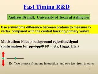
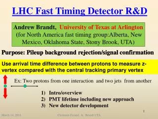
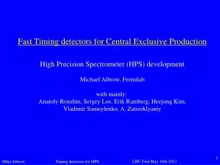
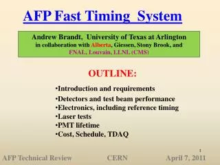
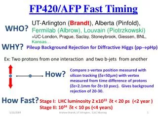
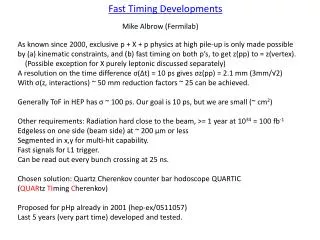
Fast Timing Developments Mike Albrow (Fermilab) As known since 2000, exclusive p + X + p physics at high pile-up is only made possible by (a) kinematic constraints, and (b) fast timing on both p’s, to get z(pp) to = z(vertex). (Possible exception for X purely leptonic discussed separately) A resolution on the time difference σ(Δt) = 10 ps gives σz(pp) = 2.1 mm (3mm/√2) With σ(z, interactions) ~ 50 mm reduction factors ~ 25 can be achieved. Generally ToF in HEP has σ ~ 100 ps. Our goal is 10 ps, but we are small (~ cm2) Other requirements: Radiation hard close to the beam, >= 1 year at 1034 = 100 fb-1 Edgeless on one side (beam side) at ~ 200 μm or less Segmented in x,y for multi-hit capability. Fast signals for L1 trigger. Can be read out every bunch crossing at 25 ns. Chosen solution: Quartz Cherenkov counter bar hodoscope QUARTIC (QUARtzTImingCherenkov) Proposed for pHp already in 2001 (hep-ex/0511057) Last 5 years (very part time) developed and tested.
To be published in J.Inst (rev.version) arXiv:1207.7248
Earlier HPS had a Gas ToF counter as well (Krzysztof Piotrzkowski) but now we only have QUARTIC: segmentation, multiple (4) measurements per track: Controls resolution, efficiency, time calibration, gives σ/2 and less stringent electronics n > √2 (important)
First generation: Angled-bar QUARTIC Isochronous at MCP. Only ~ 30% of light gets to MCP, and only some of that directly. Bars are to side of beam, go up or down. Can have x segmentation, not y Latest generation: L-bar QUARTIC All radiated light gets to detector by total internal reflection. Can have one PD/bar, e.g. SiPM Can stack bars for x and y segmentation. MCP-PMTs have a lifetime issue # photoelectrons, ~ LHC month? Being worked on. This is ATLAS AFP baseline SiPMs have a radiation damage issue. Keeping them ~ 8-10 cm above and well shielded we think this is OK (> 1 year) but need more tests. HPS baseline
2nd generation angled bar QUARTICs Electro-erosion machining (TIR) Springs & grease. Got σ(t) = 16 ps each = 11 ps pair But these MCP ~ $20K each, and may die. Also very close to beam.
L-bar QUARTIC test modules 2 boxes, each two 30mm and two 40mm bars SiPMs (Hamamatsu) readout.
2 L-bar boxes (4 modules) in test beam. Feb 2012 Can separate boxes for time shift calibration/check
Read out L-bars with waveform digitizer (scope) One event in one box:
Longer radiator bars improve time resolution Amplitude adjusted to match observed (reflectivity)
Designing 24-channel L-Bar Quartic module (Steve Hentschel, Fermilab) Housing: Thin (100 um) sheet for optical isolation (not structural). Bar arrangement: All SiPMs are in 5mm x 5mm space, with 3mm x 3mm active for bars. Light guide bars are ~ 10 cm long. Mounting for SiPM array board BEAM Bars are 20, 30 and 40 mm long. If needed one could (?) invert alternate modules to have 20+40, 30+30 and 40+20 mm. Or bars are not flush at front (not favored)
Notes: work in progress. Bottom below beam can be short. Thin wall not part of structure, only light shield. Light guides shorter if allowed. LGs can be in block of borated poly, with surrounding blocks. Front face encased in black glue, with crossed wire grids for 100 um spacing. Another x,y grid behind. Springs push matrix up.
Detector box + SiPMs + SiPM board ... reasonably in hand. Dimensions can be adjusted to fit DAQ, triggers, data transmission, integration, software etc to get in place. Thanks, Mike