AFP Fast Timing System
380 likes | 501 Vues
This report outlines the development of the AFP Fast Timing System, a collaboration involving the University of Texas at Arlington, Alberta, Giessen, Stony Brook, FNAL, and more. It emphasizes the importance of precise timing for particle interaction events, including the use of Cerenkov detectors and advanced electronics for signal confirmation and background rejection in high-luminosity environments. Key components include GASTOF and QUARTIC detectors, each aiming for 10 ps or better resolution to enhance the measurement of proton interactions through effective time differentiation.

AFP Fast Timing System
E N D
Presentation Transcript
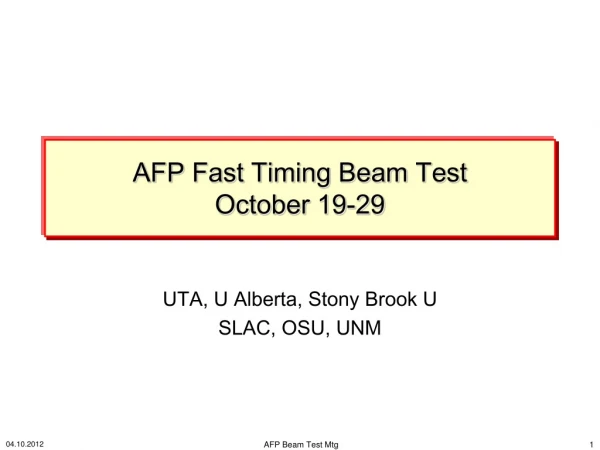
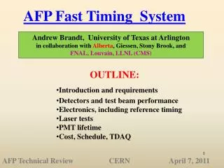
AFP Fast Timing System Andrew Brandt, University of Texas at Arlington in collaboration with Alberta, Giessen, Stony Brook, and FNAL, Louvain, LLNL (CMS) • OUTLINE: • Introduction and requirements • Detectors and test beam performance • Electronics, including reference timing • Laser tests • PMT lifetime • Cost, Schedule, TDAQ AFP Technical Review CERN April 7, 2011
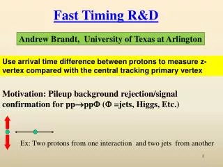
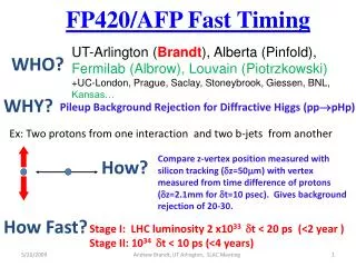
Motivation WHY? Pileup background rejection/signal confirmation Ex: Two protons from one interaction and two b-jets from another Use time difference between protons to measure z-vertex and compare with inner detector vertex. In 220 m phase this will provide crucial confirmation that any observed signal is legit How? 10 picoseconds is design goal (light travels 3mm in 10 psec!) gives ~x20 fake background rejection; Stage I: 2014 220 m few 1033 t < 20 ps Stage II: 2016 add 420 m 1034 t<10 ps How Fast? 2
Final Timing System Requirements • 10 ps or better resolution • Acceptance over full range of proton x+y • Near 100% efficiency • High rate capability (~5 MHz/pixel) • Segmentation for multi-proton timing • L1 trigger Capability • Radiation Tolerant Note: For 220 m at modest luminosity/multiple interactions, the requirements are not as stringent: 20 ps resolution, perhaps 1-2 MHz/pixel, multi-protons on same side not a significant problem, and the Level 1 trigger capability is not strictly necessary.
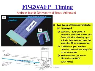
AFP Baseline Plan 30 cm • Two types of Cerenkov detector are employed: • GASTOF – a gas Cerenkov detector that makes a single measurement • QUARTIC – two QUARTIC detectors each with 4 rows of 8 fused silica bar will be positioned after the last 3D-Si tracking station because of the multiple scattering effects in the fused silica. • Both detectors employ Microchannel Plate PMTs (MCP-PMTs)
Components of AFP Fast Timing Cerenkov Radiator L1 Trigger Reference Timing HV/LV Opto-modules/ ROD 5
GASTOF Wonderful detector developed by K. Piotrzkowski (U.C. Louvain). Low index of refraction means little time dispersion, extremely accurate, radiation hard, little material for Multiple scattering From joint 2010 ATLAS/CMS CERN TB t(G1-G2)=14 ps implies 10 ps single detector resolution! BUT… only one single measurement, no segmentation, electronics challenging.
QUARTIC is Primary AFP Timing Detector UTA, Alberta, Giessen, Stony Brook, FNAL proton photons 4x8 array of 5-6 mm2 fused silica bars Only need a 40 ps measurement if you can do it 16 times: 2 detectors with 8 bars each, with about 10 pe’s per bar MCP-PMT • Multiple measurements with “modest” resolution simplifies requirements in all phases of system • 1) We have a readout solution for this option (can plug GASTOF into this) • We can have a several meter cable run to a lower radiation area where electronics will be located (without degrading overall system resolution) • Segmentation and L1 trigger is natural for this detector • Possible optimization with fibers instead of bars—discuss later
Micro-Channel Plate Photomultiplier Tube Burle/Photonis 64 channel 10 and 25 m pore MCP-PMTs have been tested extensively with test beam and laser and would be default for first stage except for lifetime issues (later)
MCP-PMT Requirements Excellent time resolution: 20-30 ps or better for 10 pe’s High rate capability: Imax= 3 A/cm2 Long Lifetime: Q= 10-20 C/cm2/year at 400 nm Multi anode: pixel size of ~6 mm x 6mm Pore Size: 10 m or smaller Tube Size: 40 mm round, 1 or 2 inch square Need to have capability of measurements in different parts of tube between 0-2 ns apart, and in same part of the tube 25 ns apart Photek 240 (1ch) Hamamatsu SL10 (4ch)
2010 CMS/ATLAS Fermilab Test Beam siPM courtesy of Ronzhin, Albrow 2 x2 mm Trigger Scint Use siPM in beam as reference for evaluating QUARTIC
2010 QUARTIC Test Beam Results Time Difference between adjacent bars is <20 ps, implies <14 ps/bar including bar, PMT, CFD! Too good to be true: due to charge sharing and light sharing, bars are correlated. Time Difference between “distant bars” 4 and 7 is 37 ps, implies 25 ps/bar (exceeds QUARTIC design goals!!!)
t(siPM – Quartic Bar) siPM-(avg of 3 quartic bars ) reduced from ~28 (for single bar) to 21ps consistent with expectations t=28 ps if Q~25 siPM <15 ps Tails due to large pulses from multiple protons saturating amps Note MCP-PMT with Quartz bar in beam “Nagoya Detector” can give ~5ps resolution
Giessen Fiber Quartic From Sabrina Darmawi’s thesis, Michael Dueren, Hasko et al • Facilitates variable bin size to optimize rate+lifetime • Simulations promising • Needs upgraded readout • electronics to fully evaluate • Prototype performance
Alberta Fiber Quartic • Preliminary Fermilab tests indicate improved time resolution over quartz bars by up to 30%, even though less total light • More studies needed including effect of fiber pigtails for better mapping onto the MCP-PMT
ALCFD ZX60 4 GHz amplifier (we use pairs of 4, 8 GHz amps in different combinations to control total amplification) We will replace with diode/amp board that fits on tube ALCFD (Alberta/Louvain Constant Fraction Discriminator): 8 channel NIM unit with mini-module approach tuned to PMT rise time, <5 ps resolution for 4 or more pe’s Stony Brook upgrade in progress to add trigger capability based on coincidence of quartz bars and basic ADC for monitoring gain
Alberta HPTDC board 12 ps resolution with pulser including non-linearity corrections. Successfully tested at UTA laser test stand with laser/10 m tube/ZX60 amp/LCFD 14 ps TDC resolution in laser tests Test beam data complicated by 19 ns bunch structure
QUARTIC HPTDC Buffering Loss rate in channel buffer for Logic core clock = 80MHz Loss rate in channel buffer for Logic core clock = 40MHz \ (4 useful channels/ chip instead of 8, but occupancy problem solved, except for ref clock see below) Concern:HPTDC designed to operate with 40 MHz clock but with occupancy of <2 MHZ; at high luminosity this might not be sufficient
Reference Timing Overview Reference timing is needed to connect two arms ~ 0.5 km apart; what we want is TL-TR, what we measure is (TL-Tref)-(TR-Tref), so need small jitter in Tref Solution has been developed by SLAC/LLNL involving phase lock loop. We need only minor modifications to use 400 MHz RF instead of 476 MHz, and circuit to convert 400 MHz to 40 MHz and multiplex clock for use in HPTDC board
Reference Timing Test Results SLAC test show 10 ps total variation over 20 C! Adding a correction for temperature, or controlling temperature of electronics (not cable) will reduce the jitter to a couple ps!)
Ref. Timing Rate Reduction • Concern: integrating reference time into DAQ since 40 MHz rate too high for occupancy restrictions • But actually we only need reference time for good events! • 1) Form a trigger based on multiplicity of CFD signals in one row -example if at least 4/8 bars have a signal 2) Only send CFD signals to HPTDC board if trigger is satisfied 3) Trigger reference time signal as well, so a chip will have 4 inputs: three bars in the row where trigger was satisfied, and the ref time signal corresponding to that row 4) possibly also keep some prescaled signals for monitoring
L1 TRIGGER • The Trigger formed in previous slide for controlling reference time rates can also be used for a L1 Trigger, instead of dedicated trigger detector • In 2014-2016 simple trigger, based on hits in timing detectors, 1 CTP term for each proton side. Use large diameter air core cables to minimize the cable delay due to latency concerns • For 420 can use several bins and combine with jet information from calorimeter
Established with DOE ADR, Texas ARP funds, beam splitter mirror LeCroy Wavemaster 6 GHz Oscilloscope filter MCP-PMT lenses laser Hamamatsu PLP-10 Laser Power Supply Laser Box
(a) Beam Mode Fiber Mode (c) (b) (d)
10 pe Time Resolution from Laser Tests Laser tests of Photonis 10 µm tube show that with sufficient amplification there is no dependence of timing on gain (low gain operation extends lifetime of tube)
Saturation from Laser Tests Saturation refers to the reduction in amplitude of the output signal due to the pores becoming busy at the rate increases (typically 1 msec recovery time/pore). This plot shows that saturation is a local phenomena, and is unaffected by multiple channels being on at the same time. No rate dependence on number of pixels hit (that’s a good thing!)
Lifetime Issues Lifetime due to positive ions damaging the photocathode is believed to be proportional to extracted charge: Q/year = I*107 sec/year Q for <I>=2 A/cm2 is 20 C/cm2/yr Can reduce this requirement with fiber detector but still off by at least a factor of 20, so developed an R&D plan to pursue this
Extending Lifetime • Inhibit positive ions from reaching photo-cathode • - Ion Barrier: aluminum film on top of MCP’s (had reduced collection efficiency side effect) so Nagoya developed new approach (between MCP’s). Factor of 5 or more lifetime increase (~3 C/cm2) for 4x4 SL10
Extending Lifetime • Minimize creation of positive ions • - Use ALD coating of MCP’s (funded SBIR proposal with Arradiance and Photonis in progress) • NEW RESULTS HERE • Harden photocathode or improve its composition • - solar blind photocathode could reduce impact of positive ions
A Long Life MCP-PMT e- Arradiance coating suppresses positive ion creation (NSF SBIR Arradiance, UTA, Photonis) Ion Barrier keeps positive ions from reaching photocathode (developed by Nagoya with Hamamatsu + + + Use Photek Solar Blind photocathode or similar (responds only to lower wavelength/more robust) photon Photocathode Improve vacuum Seal (Nagoya/ Hamamatsu) Photoelectron DV ~ 200V Dual MCP DV ~ 2000V Increase anode voltage to reduce crosstalk (UTA) Gain <105 Gain ~ 106 MCP-PMT Run at low gain to reduce integrated charge (UTA) DV ~ 500V DV ~ 200V Anode
Possible MCP-PMT Alterntive: SIPM UTA laser results consistent with UTA/FNAL TB results 16 ps for 25 pe (expected amount of Light using quartz radiator in front of SiPM) But this is not viable design, Radiation wise Would need a Quartic-like design Ronzhin, Albrow At FNAL have been studying
Funding Need to discuss with collaborators before filling this out
Manpower Need to discuss with collaborators before filling this out
Estimated Production Cost 380k$ for 1Q+1G 500k$ for 1Q+2G 680k$ incl. spares No Gastof option Removes about 100k$ Red numbers are not as well known
“Schedule” • Minimal coupling between timing sub-components means • development and production of all parts can proceed essentially in parallel. System factorizes into • Radiator: have a quartz bar solution, would prefer fibers if comparable performance • PMT: likely modified Planacon or modified SL10, both have same pixel size+layout • Electronics chain: amplifier/CFD/HPTDC • Reference Clock • Infrastructure (HV/LV/Cable) • Detector integration into Hamburg pipe • TDAQ integration
Timing TDAQ Integration L1: 2 CTP terms via one long large diameter air-core cable from each side (use ALFA integration solution) Readout: Timing integration to be done via optomodule providing data from HPTDC board to standard ATLAS RODs (whichever ROD is used by Silicon system should work). One 12 channel HPTDC board required/per 8 channels of QUARTIC (each HPTDC board has 3 chips run at 80 MHz, Providing 4 channels each; two chips have 3 Q channels and a clock while the third has 2 Q’s a G and clock). So the one GASTOF one QUARTIC option gives 48 timing readout channels/side while adding an extra QUARTIC gives 96/side. If we add the ADC that would give an ADC channel for each timing channel. So the minimal system (1Q+1G no ADC) has 96 total readout channels, while the full system would have (2Q+1G+ADC) 192+66= 258 channels
Conclusions • Substantial progress in all phases of fast timing, including integrating trigger capabilities into fast timing detector/electronics • We have a prototype fast timing system for AFP that seems to be capable of ~10 ps resolution, validated with beam and laser tests • Significant improvements in lifetime by Nagoya/Hamamatsu ; also through UTA collaborations with Arradiance, Photonis, Photek on lifetime. Solution exists for modest integrated charge (few C/cm2), 10-20 C/cm2 seems achievable on a few year timescale. • In progress: final optimization and layout of detector, electronics, PMT; evaluating radiation tolerance/needs of all components • Timing detector not on critical path assuming ATLAS approves AFP in a timely manner and R&D, production funding is obtained