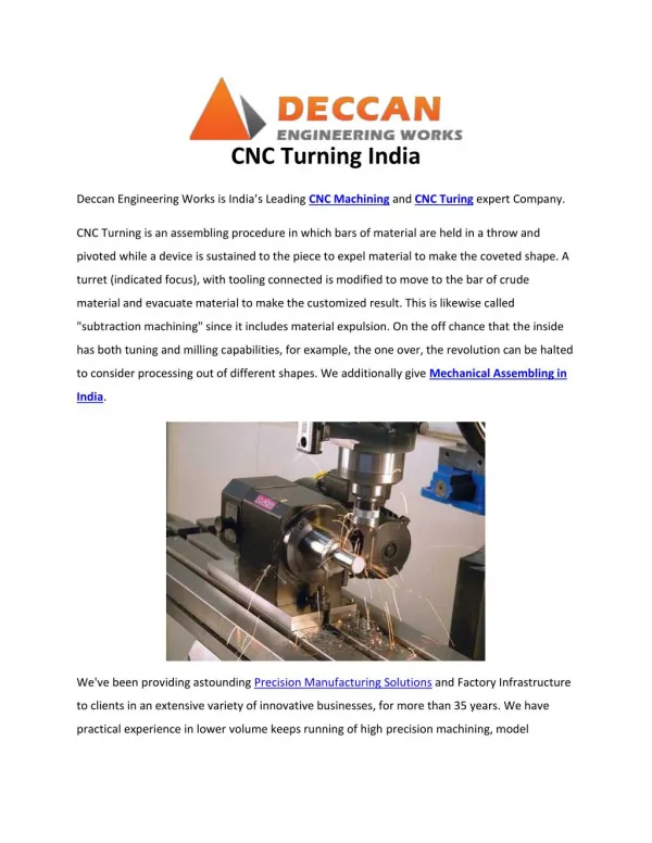
CNC TURNING
530 likes | 986 Vues
CNC TURNING. (FANUC SYSTEM). INTRODUCTION FUNDAMENTAL PRINCIPLES INSTRUCTION. 1. INTRODUCTION. Ways of Turning Parts of CNC Machine Working Methods of CNC. Ways of Turning. Conventional or Traditional Numerical Control (NC) Computer Numerical Control (CNC).

CNC TURNING
E N D
Presentation Transcript
CNC TURNING (FANUC SYSTEM)
INTRODUCTION • FUNDAMENTAL PRINCIPLES • INSTRUCTION
1. INTRODUCTION • Ways of Turning • Parts of CNC Machine • Working Methods of CNC
Ways of Turning • Conventional or Traditional • Numerical Control (NC) • Computer Numerical Control (CNC)
Difficulties with Conventional System • Complex shapes are difficult to machine • Depends on the human skill • Frequent & repeated measurements are required • Difficult to achieve consistency in product quality • High Changeover Time • Less productive hours • More scrap is generated
Current Market Demand • High quality products at Lowest cost in Minimum time with wide range of variety
Parts of NC/CNC Machine • Programming Unit • Machine Control Unit • Machine Tool Unit CNC NC
Programming Unit • Programmer • Computer system • User Interface device • Data Storage and Transfer facility
Machine Control Unit • Tape Reader • Data Buffer • Signal Output Channels to Machine Tool • Feedback channels from the Machine Tool
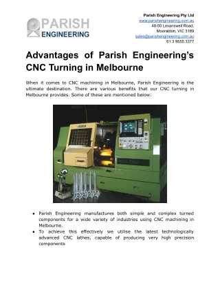
Machine Tool • Structure • Extra Rigid • Easy chip disposal System, eg: Use of Slant Bed • Thermal Resistant • Drives • AC Induction motors • DC motors
Machine Tool • Actuation System • Stepper motor/servomotor • Ball Screw & nut with support bearing • Feed back devices on closed loop system • Linear Bearing • Tool & Work handling Devices • Automatic Tool Changers (ATCs) • Turret Head • Automatic Pallet Changers • Hydraulic/Pneumatic Tool/Work Clamping System
2. Fundamental Principles • Coordinate System • Longitudinal Motion • Transverse Motion • Dimensioning System • Absolute • Incremental • Mixed • Reference System • Machine Reference • Work Reference
Instruction or program • Introduction N 10 G 00 X 50.0 Z 25.0 ; Block Words End of Block Block No. G 00 Data Address
Linear Path Function • G00 Rapid Linear Movement • G01 Linear Movement with Programmed Feed Rate Writing Format G00 X 50.0 Z2.0; G01 X 50.0 Z2.0 F0.1;
Example Program [BILLET X55.0 Z40.0; G99 G21 G40; S1000 M13; M06 T0101; G00 X55.0 Z2.0; G01 X55.0 Z0.0 F0.2; G01 X -1.0 Z0.0 F0.1; G00 X 55.0 Z2.0; G00 X20.0; G01 X20.0 Z-10.0 F0.1; G01 X40.0 Z-10.0; G01 X40.0 Z-25.0; G01 X50.0 Z-25.0; G01 X50.0 Z-35.0; G01 X55.0 Z-35.0; G00 X55.0 Z2.0; G28 U0 W0; M30; 0,0
Circular Path Function • G02 Circular Movement Clockwise (CW) • G03 Circular Movement Counter Clock Wise (CCW) Writing Format G03 X 25.0 Z-10.0 R5.0 F0.1; G02 X 25.0 Z-10.0 R5.0 F0.1;
Example Program [BILLET X55.0 Z40.0; G99 G21 G40 S1000 M13; M06 T0101; G00 X38.0 Z2.0; G01 X38.0 Z0.0 F0.2; G01 X -1.0 Z0.0 F0.1; G00 X 38.0 Z2.0; G00 X10.0; G01 X10.0 Z-10.0 F0.1; G02 X18.0 Z-14.0 R4.0; G01 X18.0 Z-19.0; G03 X24.0 Z-22.0 R3.0; G01 X24.0 Z-30.0; G01 X38.0 Z-30.0; G00 X38.0 Z2.0; G28 U0 W0; M30;
Various Important Addresses • O: Used to represent program number • N: Used to represent Block Number • G: Are known as preparatory codes, used to prepare the machine for a particular function. • X, Y, Z : Represents Absolute coordinates • U, V, W: Represents Incremental coordinates • I, J, K: Specifies coordinate of centre of arc • R: Represents radius of arc • S: Represents Spindle Speed • T: Specifies Tool Number • M: Miscellaneous Functions • P, Q: Used to represent start & end block number in a subroutine cycle. • F: Represents Feed
G71 (Turning Cycle) 1st Line of G71: U – Specifies the depth of cut in each pass R – Retract amount after every pass 2nd Line of G71: P – Specifies the start block number Q – Specifies the end block number U – Specifies the finishing allowance in X W – Specifies the finishing allowance in Z G70 – Finishing Pass Writing Format G71 U1.0 R1.0; G71 P10 Q20 U0.5 W 0.5 F0.25; N10 G00 X…..; ……. ……. ……. N20 ……..; G70 P10 Q20 F0.15;
Example Program …… N10 G00 X38.0 Z2.0; N20 G71 U1.5 R0.5; N30 G71 P40 Q130 U0.5 W0.2 F0.35; N40 G01 X16.0; N50 G01 Z0.5; N60 G01 X20.0 Z 1.5; N70 G01 Z-30.0; N80 G01 X 23.0; N90 G03 X25.0 Z-24.0 R1.0; N100 G01 X30.0 Z-65.0; N110 G01 Z-75.0; N120 G02 X36.0 Z-77.0 R3.0; N130 G01 X38.5; N140 G70 P40 Q 130; ….
Example Program [BILLET X38.0 Z40.0; G99 G21 G40 S1000 M13; M06 T0101; G00 X39.0 Z2.0; G01 X38.0 Z0.0 F0.2; G01 X -1.0 Z0.0 F0.1; G00 X 38.0 Z2.0; G71 U1.0 R0.5; G71 P10 Q20 U0.5 W0.1 F0.35; N10 G00 X10.0; G01 X10.0 Z-10.0 F0.1; G02 X18.0 Z-14.0 R4.0; G01 X18.0 Z-19.0; G03 X24.0 Z-22.0 R3.0; G01 X24.0 Z-30.0; N20 G01 X39.0 Z-30.0; G70 P10 Q20; G00 X39.0 Z2.0; G28 U0 W0; M30;
Types of Instructions • Movement Instruction • G00, G01, G02, G03 • Machine Instruction • M00, M02, M03, M04, M05, M06, M08, M09, M30 • Tool Instruction • T0101 • Technological Instruction • Cutting Speed • Spindle Speed • Feed • Dimensional Instruction • Metric • Inch
G- Codes • G28: Return to Machine Reference Point Writing Format: G28 U0 W0; • G20: Programming in Inches • G21: Programming in Metric (mm)
M-Codes • M00: Program Stop, starts again when cycle start is pressed • M01: Optional Stop • M02: Program Reset • M30: Program Reset & Rewind • M03: Spindle Start in Clockwise Direction • M04: Spindle Start in Anti Clockwise Direction • M05: Spindle Stop • M06: Command Tool Change • M07/M08: Coolant ON • M09: Coolant OFF • M10: Chuck Open • M11: Chuck Close • M13: Spindle ON (CW) & Coolant on • M14: Spindle ON (CCW) & Coolant on • M25: Tailstock Quill Extend • M26: Tailstock Quill Retract • M98: Subprogram Call • M99: Return to Main Program
G72 (Facing Cycle) 1st Line of G72: W – Specifies the depth of cut in each pass (in Z Direction) R – Retract amount after every pass 2nd Line of G71: P – Specifies the start block number Q – Specifies the end block number U – Specifies the finishing allowance in X W – Specifies the finishing allowance in Z G70 – Finishing Pass Writing Format G72 W1.0 R1.0; G72 P10 Q20 U0.5 W 0.5 F0.25; N10 G00 X…..; ……. ……. N20 ……..; G70 P10 Q20 F0.15;
Tool Offset The Distance traveled by the tool cutting edge from the machine reference point to the work reference point in a particular axis is termed as “Tool Offset”. For turning tool offset is measured in both the directions i.e. ‘X’ & ‘Z’.
Modal & Non Modal G-Codes • The G-Codes whose effect continue in the program once specified until it is cancelled or overridden by another code are known as “MODAL”. Eg: G00, G01, G02, G03 etc. • The G-Codes whose effect only in the block where it is defined are known as Non-Modal Codes. Eg: G04
Groups of G-Codes • The G-Codes are grouped under various groups. Each group contains similar kind of codes and their effect can only be overcome/nullified by the use of another code of same group. Group ‘0’ : G04, G10, G27, G28, G29, G30, G31 G50, G65, G72, G73, G74, G75, G76 Group ‘1’ : G00, G01, G02, G03, G90, G92, G94 Group ‘2’ : G66, G67, G96, G97 Group ‘4’ : G70, G71 Group ‘6’ : G20, G21 Group ‘7’ : G40, G41, G42 Group ’11’ : G98, G99
Different Modes of Machining • Manual Data Input (MDI) Mode Tasks: Single or few line simple program can be written temporarily and executed only once. After executing the written lines of program are deleted from the machine memory. • Auto Mode • Continuous Auto Runs the complete program from beginning to the end once the cycle start button is pressed. • Single Auto Runs the program block by block i.e. only one block of the program is executed by pressing the cycle start button once.
Feed (Method Selection) During Lathe working the feed of the tool can be defined by two different Methods. • mm/minute • mm/revolution While programming on CNC Machine the feed methods can be selected by: mm/minute : G98 mm/revolution : G99
Use of G96, G97 & G50 While Programming for CNC Turning (Fanuc)
Meaning of G96, G97 & G50 • Significance • Writing Format • When to use
Meaning • G96: Specifies constant cutting speed (m/min) • G97: Specifies constant spindle RPM • G50: Limits the maximum Spindle Speed
Cutting Speed & RPM • Cutting Speed: It is defined as the speed with which the periphery of workpiece passes over the cutting edge of the tool. Its unit is m/min. It depends on following quantities: • Material of Workpiece • Material of cutting tool • RPM: It is the speed with which the spindle is rotating. Its unit is revolutions per minute. • The Cutting Speed & RPM are related by the following formula: V = πDN/1000, where V is Cutting Speed, D is Diameter of Job, N is RPM.
Writing Format • Constant Cutting Speed • G50 S4000; (here S represent Limit for maximum spindle speed) • G96 S100 M03; (here S represents the Cutting Speed defined in m/min) • Constant Spindle Speed • G97 S2500 M03; (here S represents constant Spindle Speed)
Crest Root Threading
Threading Calculation for Thread Height: h = 0.61343 x pitch Core Diameter, d = D – 2x h
Requirements for Threading • Select Proper Cutting Tool: Angle & Shape of cutting tool should be same as that of the cross-section of thread. • Make Chamfer prior to threading: At the start of thread. • Make Groove prior to threading: At the end of thread.
Threading Cycle (G76) [BILLET X50.0 Z60.0; G99 G21 G40; S500 M13; G28 U0 W0; M06 T0101; G00 X51.0 Z2.0; G71 U1.5 R0.5; G71 P10 Q20 U0.5 W0.5 F0.15; N10 G01 X20.0 ; G01 X24.0 Z-2.0; N20 X24.0 Z-42.0; G70 P10 Q20; G28 U0 W0; M06 T0606; G00 X24.5 Z2.0; G76 P031560 Q50 R0.15; G76 X20.319 Z-38.0 P1840 Q150 F3.0; G28 U0 W0; M30; 1ST Line of G76: Pxxyyzz: xx: No. finishing Passes yy: Chamfering amount at the end of thread zz: Angle of tool tip (in deg) Q….: Minimum depth of cut in each pass (in micron) R….: Finishing allowance (in mm) 2nd Line of G76: X…..: Core diameter of thread (mm) Z….: Length of thread (mm) P….: Height of thread (in micron) Q…..: Depth of cut in first pass (in micron) F….. : Pitch of thread (in mm)
Tool Nose Radius Compensation (TNRC) G41/G42/G40
Importance Actual Path Generated (Material Left on Tool Path) Programmed Path
Specifying TNRC • Decide the Direction of TNRC • G41 (Left)/G42 (Right) : Program • Decide the Amount of TNRC • Value of Tool Nose Radius : Tool Offset Page • Decide the Imaginary Tool Nose Position (Tool Type) : Tool Offset Page • Cancel the TNRC (G40): Program
Direction of TNRC G42 (RIGHT) G41 (LEFT)
Amount of TNRC Radius of Tool Nose
How to specify in a program WITHOUT TNRC [BILLET X38.0 Z40.0; G99 G21 G40 S1000 M13; G00 X 38.0 Z2.0; G71 U1.0 R0.5; G71 P10 Q20 U0.5 W0.1 F0.35; N10 G00 X10.0; G01 X10.0 Z-10.0 F0.1; G02 X18.0 Z-14.0 R4.0; G01 X18.0 Z-19.0; G03 X24.0 Z-22.0 R3.0; G01 X24.0 Z-30.0; N20 G01 X39.0 Z-30.0; G70 P10 Q20; G00 X39.0 Z2.0; G28 U0 W0; M30; WITH TNRC [BILLET X38.0 Z40.0; G99 G21 G40 S1000 M13; G00 X 38.0 Z2.0; G71 U1.0 R0.5; G71 P10 Q20 U0.5 W0.1 F0.35; N10 G00 G42 X10.0; G01 X10.0 Z-10.0 F0.1; G02 X18.0 Z-14.0 R4.0; G01 X18.0 Z-19.0; G03 X24.0 Z-22.0 R3.0; G01 X24.0 Z-30.0; N20 G01 G40 X39.0 Z-30.0; G70 P10 Q20; G00 X39.0 Z2.0; G28 U0 W0; M30;