Download
1 / 31
310 likes | 417 Vues
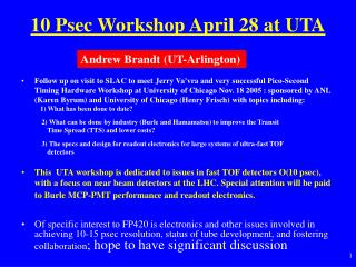
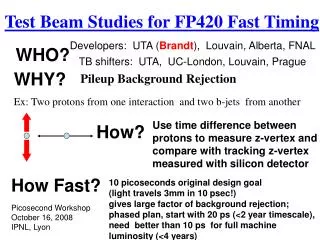
Test Beam Studies for FP420 Fast Timing. Developers: UTA ( Brandt ), Louvain, Alberta, FNAL. WHO?. TB shifters: UTA, UC-London, Louvain, Prague. WHY?. Pileup Background Rejection. Ex: Two protons from one interaction and two b-jets from another.

E N D
Test Beam Studies for FP420 Fast Timing Developers: UTA (Brandt), Louvain, Alberta, FNAL WHO? TB shifters: UTA, UC-London, Louvain, Prague WHY? Pileup Background Rejection Ex: Two protons from one interaction and two b-jets from another Use time difference between protons to measure z-vertex and compare with tracking z-vertex measured with silicon detector How? How Fast? 10 picoseconds original design goal (light travels 3mm in 10 psec!) gives large factor of background rejection; phased plan, start with 20 ps (<2 year timescale), need better than 10 ps for full machine luminosity (<4 years) Picosecond Workshop October 16, 2008 IPNL, Lyon
Fast Timing Is Hard! ISSUES Time resolution for the full detector system: 1. Intrinsec detector time resolution 2. Jitter in PMT's 3. Electronics (AMP/CFD/TDC) • 3 mm =10 ps • Detector • Phototube • Electronics • Reference timing • Rad Hardness of detector, phototube and electronics, where to put electronics in tunnel • Lifetime and recovery time of tube, grounding • Background in detector and MCP • Multiple proton timing
FP420 Baseline Plan 2 QUARTICs 1 GASTOF Lots of 3D silicon • Two types of Cerenkov detector are employed: • GASTOF – a gas Cerenkov detector that makes a single measurement • QUARTIC – two QUARTIC detectors each with 4 rows of 8 fused silica bar allowing up to a 4-fold improvement over the single bar resolution • Both detectors use Micro Channel Plate PMTs (MCP-PMTs)
The Detectors : 1) GASTOF (Louvain) Not so much light since use gas, but full Cerenkov cone is captured. Simulations show yield of about 10 pe accepted within few ps! 1 measurement of ~10 ps
The Detectors : 2) QUARTIC proton 4x8 array of 6 mm2 fused silica bars UTA, Alberta, FNAL Only need 40 ps measurement if you can do it 16 times (2 detectors with 8 bars each)! photons
First TB Results ( Fall 2006) G1-G2 For QUARTIC bar 110 psec Efficiency 50-60% For events with a few bars on see anticipated √N dependence <70 psec/Gastof (Burle 25 um 8x8 tube, 4 pixels) >90% efficiency, dominated by CFD resolution (used Ortec 934)
March 2007 Test Beam (t)=45 ps (t)=35 ps Threshhold discrimination CFD algo simulated QUARTIC 80 ps/bar (15 mm bar) 80% efficient if G1=G2 then t=25 ps each, but G1 has faster tube (Hamamatsu 6 m pore vs 25 m Burle) and better mirror; extract resolution G1=13 ps G2=32 ps, initial estimate 80% efficient
Latest QUARTIC Prototype HC HH HE Testing long bars 90 mm (HE to HH) and mini bars 15 mm (HA to HD) Long bars more light from total internal reflection vs. losses from reflection in air light guide, but more time dispersion due to n()
QUARTIC 15 mm bar/75 mm guide 20 ps ~ 5 pe’s accepted in 40 ps 20 ps
QUARTIC 90 mm bar/0 mm guide 40 ps 40 ps ~ 10 pe’s accepted in 40 ps 40 ps
June 2008 Test Beam • In between Mar 2007 and June 2008 had two largely unsuccessful test beams due primarily to tracking failures; for the June run we planned to be secondary user for first week with 3dsil group, and primary user for 2nd week, in order to ensure good tracking • Planned laser tests at Louvain prior to TB run; mixed success • Planned to have fully functional analysis program, mixed success • Main goals of June run to validate detector design, including using tracking for efficiency measurement
QUARTIC: Photonis Planacon 10 m pore 8x8 Gastof: Hamamatsu 6 m pore single channel or equivalent Photek MCP-PMT Fast Scope Preamplifier LCFD SMA SMA Lemo SMA Fast Scope Electronics Louvain Custom CFD (LCFD) • Experiment channel Mini-circuits ZX60 6 GHZ or equivalent HPTDC board (Alberta) interfaces to ATLAS Rod For GASTOF replace CFD/TDCwith single photon counter (b) or (c) TB channel
LCFD Luc Bonnet (Louvain) tuned LCFD mini-module to Burle planacon; 12 channel NIM unit
June 2008 Test Beam Setup fast timing Cerenkov 3d-sil+Bonn telescope trigger paddles comment on alignment
FP420 Timing Setup G2 G1 Q1 Amplifiers
Data Acquisition • Lecroy 8620A 6 GHz 20 Gs (UTA) • Lecroy 7300A 3 GHz 20/10 Gs (Louvain) • Remotely operated from control room using TightVNC • Transfer data periodically with external USB drive UTA funding from DOE ADR grant and Texas ARP grant
Good Trigger is Important Spray event add veto
Coherent Noise! channels in adjacent rows
Good Event 5 ns/major division
Online Screen Capture one histo is 10 ps per bin others are 20 ps histogram delta time between channels FWHM<100 so /2.36 ->dt~40 ps
overflow -> switch from 100 to 200 mv scale acceptance Offline Analysis • Too cumbersome, not getting results in timely manner • I implement streamlined approach + round the clock analysis shifts (one data taking shifter, one analysis shifter: Nicolas, Vlasta, Shane) -start with basics -plot pulses -pulse heights -low threshold cut -raw times -time differences -add tracking later
Determining Pulse Time Hamamatsu(G1) Burle (HF) LCFD (HFc) Linear fit, use 50% time
QUARTIC Long Bars after LCFD Dt 56.6/1.4=40 ps/bar including CFD! Time difference between two 9 cm quartz bars after constant fraction discrimination is 56 ps, implies a single bar resolution of 40 ps
LCFD Resolution Split signal, take difference of raw time and CFD time-> LCFD resolution <27 ps This implies detector+tube ~30 ps
Tracking /Scope Synchronization All tracks • Early tracking results: • 88% of tracks • 170<x<260 have HEc • bar on • 98% have HF on (lower • threshold) • Timing does not seem to • depend on whether or not • there is a track (efficiency • is high)-> can use all • non-tracking data HEc On 6mm
HF Efficiency fraction of events with good track and HF bar on as a function of track position 6 mm
GASTOF Displaced 19 mm See Schul talk for more details All tracks Multiple scattering effects in 400 um wide, 30 cm long stainless steel edge of GASTOF (cause veto)! 1mm depletion implies tracking projection issues, detector tilted slightly, or both GASTOF On dip ~1 mm wide edge
What to Measure: QUARTIC • Data taking still in progress (lost a graduate student) • Dependence of efficiency, pulse height, time resolution on bar type and position, HV, 0 vs 1 vs 2 amps, as f(scope resolution 50 vs 100 ps, 3 vs 6 ghz) • Before and after shift in veto counter • Also have some 25 m tube data • ``Time track’’ using all channels
QUARTIC vs GASTOF • Do we need both? • G one (or two) measurements 10-20 ps need to figure out readout integration • Q multiple measurements 40 ps each 10-20 ps overall, some multi-proton capability, integration into readout through HPTDC, need to demonstrate N improvement of 8 bars • Different background characteristics • I think answer is still yes
Summary • June TB two+ weeks of running, tremendous effort • 100+Gb of scope data, sizable fraction synchronized with tracking from Bonn telescope • Analysis in progress • Demonstrated good data, now finalizing results, plan to write a paper this year • I believe that we have two viable, complementary detector concepts • Will need more laser tests, simulation and test beam before design is finalized • Working on building a U.S. ATLAS collaboration for Phase 1+2 funding (new effort welcome!)
ATLAS/CMS MCP-PMT Needs • For current QUARTIC design, need about a dozen 10 m pores 64 channel Planacon (or Photek equivalent) • High Rate capability (at 420 m 1% of interactions have a scattered proton). Start with 13 MHz (75 nsec bunch spacing). Few interactions per crossing, <1 MHz over 12.5 cm2 so should be okay. At max luminosity, 25-30 interactions/crossing at 40 MHz 40 MHz -> 10 MHz over area, may be okay? • 220 m, situation is ~3 times worse! • Need high current capability to improve lifetime of tube: I calculate 10 C over tube in 100,000 hours (1/5 of year) at low luminosity (using 80 pe/event and gain of 106 ) • Better grounding • Dropped faceplate? • Other minor improvements? • Phase 1 vs phase 2