Download

1 / 32
320 likes | 436 Vues
The DVP-525 is a cutting-edge 16-bit Delta-Sigma Analog-to-Digital Converter designed for high-quality voice applications, such as VoIP and digital telephony. This project involves comprehensive design tasks including architecture definition, MATLAB simulations, behavioral and structural Verilog simulations, and an initial floorplan based on component estimates. The design aims for ultra-low power consumption, estimated at around 5 mW, and includes critical hardware elements like the modulator, lowpass filters, and a clock divider. It is engineered to meet the increasing demands of the digital voice processing market.

E N D
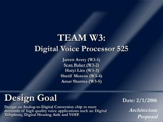
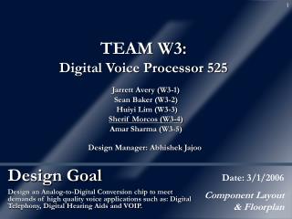
TEAM W3:Digital Voice Processor 525 Jarrett Avery (W3-1) Sean Baker (W3-2) Huiyi Lim (W3-3) Sherif Morcos (W3-4) Amar Sharma (W3-5) Design Manager: Abhishek Jajoo Design Goal Date: 2/8/2006 Size Estimates/ Floorplan Design an Analog-to-Digital Conversion chip to meet demands of high quality voice applications such as: Digital Telephony, Digital Hearing Aids and VOIP.
Status • Design Proposal • Project chosen: 16 bit Delta-Sigma ADC • Basic specs defined • Architecture • Matlab Simulated • Behavioral Verilog Simulated • Structural Verilog – Done, but not simulated • Schematic • Analog components created & simulated with digital behavioral Verilog models • Floorplan • Initial floorplan created based on estimates of component areas • Layout • Simulation / Verification
In Case You Forgot…(A Summary of Last Week) • Applications of the DVP-525 • VoIP, Digital Telephony, Encrypted Communications • Digital Hearing Aids • How the DVP-525 works: • Uses Delta-Sigma modulation of input signal and decimation to convert an analog signal into 16 bit binary numbers
Algorithm Detail Lowpass Filter Analog to Digital Conversion (Delta-Sigma Modulator) Decimation (Sinc Filter, Downsample) Analog Input Digital Output Measure Peak Amplitude (Peak Input Indicator) Digital Peak Indicator
Hardware That Makes it Happen(Modulator) Integrators Comparator
Algorithm Detail Lowpass Filter Analog to Digital Conversion (Delta-Sigma Modulator) Decimation (Sinc Filter, Downsample) Analog Input Digital Output Measure Peak Amplitude (Peak Input Indicator) Digital Peak Indicator
Algorithm Detail Lowpass Filter Analog to Digital Conversion (Delta-Sigma Modulator) Decimation (Sinc Filter, Downsample) Analog Input Digital Output Measure Peak Amplitude (Peak Input Indicator) Digital Peak Indicator
Clock Divider • New component added to digital portion of design • Takes as input the oversampled clock and outputs the Nyquist clock • We are using an oversampling factor of 256 • So, need to divide oversampled clock by 256 • Implemented with a 7-bit counter and a T (toggle) flip-flop • Every time counter overflows (reaches 128), flip-flop toggles (Cout connected to flip-flop’s clock) • This produces a clock with 1/256 the input frequency
Simulation – MatLab • First modeled the modulator in the time domain, and fed it simple sine wave input:
Simulation – MatLab (cont’d) • Then fed the bitstream created by the modulator into the decimator:
Simulation (cont’d) • Now, we have simulated entire design in a mixed-signal environment • Analog portion represented by generic components • Digital portion represented by behavioral Verilog code • Simulated together in Cadence using AHDL
Simulation (cont’d) • Simulated behavioral models of PII function & clock divider in ModelSim • Verified generation of Nyquist clock by clock divider module • Verified updates of maximum & minimum values of sinc filter output by PII function module
Transistor Count Estimates • Analog • 3 x Analog Op Amps, 3 x 24 = 72 • Resistive/Capacitive Elements • Digital • 8 x 18-bit registers, 8 x 400 = 3200 • 1 x 12-bit register, 1 x 260 = 260 • 8 x 18-bit adders, 8 x 510 = 4080 • 1 x 24-bit counter, 1 x 870 = 870 • 1 x 7-bit counter, 1 x 250 = 250 • 1 x 12-bit equality function, 1 x 120 = 120 • 2 x 18 bit muxes, 2 x 110 = 220 • Misc logic = 200 • Total = 9,300 transistors
Initial Floorplan Total Area = 77, 750 sq μm
Power Considerations • How much power will our chip consume? • Ultra low-power hearing aids burn about 1 mW • Do we need special low-power adders? • Brandt & Wooley ’94 suggested using static CMOS ripple carry adders • Looked at other papers proposing low-power, high-performance adders • These designs were more geared toward other applications using clocks over 100 MHz • Since we’re using a 5 MHz clock & a 20 KHz clock, ripple carry is ideal for us
Power Considerations (cont’d) • Brandt & Wooley listed their chip’s power consumption at 6.5 mW at 3V • Our design much smaller and runs at much lower speed (20 KHz vs. 176 KHz) • We’ll be using 1.8V source • Estimate chip’s total power at about 5 mW • Sinc filter – 1 or 2 mW • PII Function & Clock Divider – 1 mW • Analog Portion – 2 or 3 mW
Analog Device Sizes • Some concern about sizing of analog components • Average size of analog transistors = 30 μm x 0.5 μm = 15 sq μm • Average size of analog resistors (500 Ω) = 24 μm x 600 nm = 14.4 sq μm • Average size of analog capacitors (1 pF) = 30 μm x 30 μm = 900 sq μm • May have to look at alternatives
Design Decisions • Decided on using static CMOS ripple carry adders • Decided on modifying PII function to allow user to input time period to wait before clearing max and min registers • Using 24-bit counter with 20 KHz clock to compare against wait period • Upper 12 bits of counter compared to wait period • Gives wait period range of 200 ms to 14 minutes • Decided on generating our own Nyquist clock (20 KHz) • If clock needs to be cleaner, we can always go back to assuming two clock inputs • Decided on analog component values (RC values)
Problems and Questions • Have we bitten off more than we can chew? • 9,000+ transistors is a lot for 2-3 digital designers • Much of transistor count taken up by repeated modules like adders, registers • Can always reduce design (PII function, clock divider) • Analog device sizes • Do we need to change our design?
Results • More comfortable with overall design • More familiar now with mixed analog/Verilog simulations • Ready to move forward with design • Structural Verilog simulations • Overall schematic including both analog & digital portions of design • Topology, gate sizing, RLC selection for analog parts • Layout