Download

1 / 15
160 likes | 336 Vues
This work has been supported by the European Social Fund within the project «Support for the implementation of doctoral studies at Riga Technical University». . Using Functional Characteristics to Analyze State Changes of Objects. Uldis Donins, Janis Osis, Erika Asnina and Asnate Jansone

E N D
This work has been supported by the European Social Fund within the project «Support for the implementation of doctoral studies at Riga Technical University». UsingFunctionalCharacteristics to AnalyzeStateChangesofObjects Uldis Donins, Janis Osis, Erika Asnina and AsnateJansone RigaTechnicalUniversity Baltic DB & IS 2012, July8-11, 2012-Vilnius, Lithuania
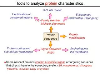
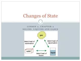
Introduction • The behaviour of an object over time could be surmised by analysing system Use case descriptions, Activity diagrams, or other software design artefact • To avoid surmising the state change of objects in system, UMLState diagram is used • Instead of analysing the problemdomain, software developers set the main focus on software design thus leading to a gap between the problem domain and its supporting software • This issue can be overcome by formalizing the very beginning of the software development lifecyclebyusingTopologicalFunctioningModel (TFM) • The purpose of this research is to strengthen theapplicationof TFM with formal development of State diagrambyenabling transformation from TFM to it and eliminating the gap between problem domain and solution 2
Related Works • The current state of the art of UML based software development approaches sharescommon viewpoint of the application of State diagrams within software development process: • State diagrams are developed by analysing Use cases, • One state diagram per class or object, and • They should be developed for each most important object within the system. 3
QuestionsRemainingOpen • Previouslymentioned three statements raise a set of ambiguousness and questions: • The Use cases cannot be considered as a complete problem domain representation and a formal connection between problem domain and the solution. • The application of Use cases to develop other diagrams (such as State) depends much on the designers’ personal experience and knowledge • Thisleavesfollowing questionsopen: • How to formally eliminate and overcome the gap between problem domain model and the design models?, and • What are “most important objects” and how to formally identify them? • To overcome these issues the TFM is applied within software development process as a rootmodelforanalyzingandunderstandingfunctioningcharacteristicsofproblemandsolutiondomains 4
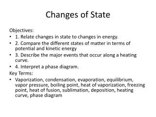
Analysis of Objects State Changes and Transitions • Formalstatechange analysis of objects consists of thefollowing activities: • TFM development, • Domain model analysis and design, and • Object state change and transition analysis. 5
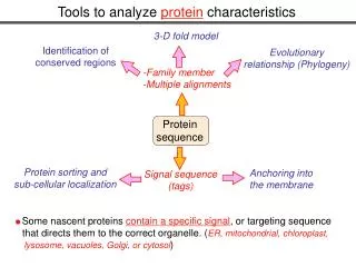
TopologicalFunctioningModelDevelopment (1) • During this activity a TFM representing complete functioning of the problem domain is developed • Afterwards the TFM is used as a source for development of other diagrams thus overcoming the gap between problem and solution domains • TFM is developed by completing following four steps: • Step 1: Definition of physical or business functional characteristics, • Step 2: Introduction of topology, • Step 3: Separation of TFM from topological space, and • Step 4: Identification of logical relations. 6
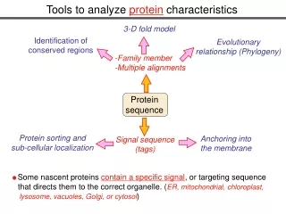
Domain ModelAnalysisand Design(1) • Domain model analysis and design is based on the Topological class diagram and consists of two steps. • Step 1: Analysis of objects and their communication • Basedon the TFM transformation into Communication diagram • When transforming TFM into Communication diagram the following are used: • Functional features – source for lifeline identification and message sending from object to object, • Topological relationships – determines the message sender and receiver as well as the message sending sequence, and • Logical relations – shows the message sending concurrency. 8
Domain Model Analysis and Design (3) Dependency TFM Generalization Association Communicationdiagram Topological (cause-and-effect)relationship Mainfunctioningcycle 11 11
Object State Change and Transition Analysis (2) • The first action is to scale down TFM which is performed by removing features which does not represent the object under consideration but in the same time retaining cause-and-effect relations. Forexample, assumethat: • TFM consists of three features : A→B→C • The A and C represent the same object while B represents another object, thus resulting TFM is as follows: A→C. • States for each class are obtained from the functional features of TFM. • If the execution of functional feature involves the change of the corresponding object’s state, then the state attribute has value, otherwise the value is not set. • State transitions are obtained by transforming cause-and-effect relationship between functional features. • The special states (initial state and final state) are added to the obtained State diagram as inputsandoutputsofdownscaled TFM. 13
ExampleofObjectState Change&TransitionAnalysis (1) • Example is based on a case study in which TFM is developed for enterprise data synchronization system. • Partoffunctionalfeatures that specify the new state for object named “Scheduler”: 15
Conclusions • The main goal of this research is to do formal development of State diagram by analysing functional characteristics of a problem domain • The elaborated State diagram developmentmethodproposes a way on how to formally overcome the gap between problem domain and solution domain • The first one is represented by TFM which shows the complete functioning of a problem domain and • The latter one is obtained by transforming TFM of a problem domain. • Moreover the proposedapproachenablesformal identification of the most important objects and classes within system – they are denoted by TFM: • functional features that are included into main functional cycle specify these objects and classes • In contrast, the reviewed UML modelling driven methods relies that the designers’ personal experience and knowledge is sufficient to identify most important objects within system • In addition the example described in paper shows State diagram development for the case study in which enterprise data synchronization system has been developed by using proposedmodellingapproach 17