Download
1 / 18
180 likes | 313 Vues
This study discusses advancements in vertical position control of NSTX, focusing on improved detection methods to mitigate vertical displacement events (VDEs) at higher aspect ratios. It identifies key challenges and proposes a strategy to enhance control systems, involving the use of improved observer techniques and optimized vertical control gains. The research highlights the importance of selecting appropriate measurement loops and balancing sensitivity against linearity for more effective plasma position estimation. The findings aim to support successful optimization of future experimental scenarios.

E N D
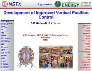
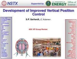
NSTX Supported by Development of Improved Vertical Position Control College W&M Colorado Sch Mines Columbia U CompX General Atomics INL Johns Hopkins U LANL LLNL Lodestar MIT Nova Photonics New York U Old Dominion U ORNL PPPL PSI Princeton U Purdue U SNL Think Tank, Inc. UC Davis UC Irvine UCLA UCSD U Colorado U Illinois U Maryland U Rochester U Washington U Wisconsin S.P. Gerhardt, E. Kolemen Culham Sci Ctr U St. Andrews York U Chubu U Fukui U Hiroshima U Hyogo U Kyoto U Kyushu U Kyushu Tokai U NIFS Niigata U U Tokyo JAEA Hebrew U Ioffe Inst RRC Kurchatov Inst TRINITI KBSI KAIST POSTECH ASIPP ENEA, Frascati CEA, Cadarache IPP, Jülich IPP, Garching ASCR, Czech Rep U Quebec ASC XP Group Review
XP in 2010 Showed that Vertical Position Control can be Lost at Higher Aspect Ratio • 1 Fiducial (green) and 8 shots at higher aspect ratio. • Black cases vertically stable, the colored ones have VDEs. • VDE is always triggered when li=0.6. • This is not a particularly high value. • Would preclude use of the scenario for many XPs. • Other instances of vertical stability problems. • Egemen’s squareness XP. • Ron Bell’s DIII-D comparison XP. • After every nearly every locked mode and RWM. • Motivates improvements to the n=0 controller.
Interesting Scenarios for the Upgrade Will Push Against These Limits Ask for high-kappa at values of li comparable to present values. Ask for high-kappa at even larger A.
Strategy To Fix Problem • Improve the detection of small vertical motion. • “dZ/dt Observer” • Re-optimize vertical control gains with improved observer. • If necessary, use RWM coils for vertical control.
Vertical Position Controller is a PD Controller Using Loop Voltages for dZ/dt Measurement • Proportional controller is simply the Isoflux shape control algorithm: • Fast derivative controller is based on the up-down loop voltage difference. • The underlying assumption is that the plasma vertical position can be measured by only 2 loops: • Thesis: Using more/different loop voltages will lead to a better estimation of the plasma position. • Eliminate n=1 pickup from random loop orientation problems. • More information for shapes that are distorted. • Proper selection of measurement loops has been emphasized in the literature: • Ward & Hofmann, Nuclear Fusion 34, 401 (1994) • Pomphrey, Jardin, and Ward, Nuclear Fusion 29, 465 (1989) • Albanese, Coccorese, and Rubinacci, Nuclear Fusion 29, 1013 (1989) • C. Kessel, et al., Nuclear Fusion 41, 953 (2001)
Inboard Side Loops Were Chosen in a Study for ITER Control in Kessel, et al. Perturbed flux pattern from 10 cm downward shift • s What is the common perturbed flux pattern for NSTX cases? C. Kessel, et al., Nuclear Fusion 41, 953 (2001)
Plasma Equilibrium Determines the Most Sensitive Loop Pair Compute pairs of equilibria displaced by 2 cm: y1 and y2 Subtract them from each other (Surrogate for the voltage.): dy =y1–y2 Compute the expected flux difference: dyUD =dy-dy(z=-z) No single pair is optimal for detecting vertical motion.
Use a Database of Equilibria to Determine Which Loops are Best For Detecting Vertical Motion • Consider ~290 NSTX equilibria. • Majority from LRDFIT and EFIT reconstructions. • Include currents in the passive plates, mode non-rigidity. • Minority generated with ISOLVER • Computed the flux at the various flux loop locations. • Fit the magnetic axis location to a function: • Only use equilibria with |ZP|<20 cm • Find coefficients a from: • linear SVD solution, or • constrained optimization • Prevent any single value a from becoming too large.
Studies Show That Loops on the Center Column are Most Linear...But Least Sensitive • CSC loops have less relative coupling to plates, are more linear. • But are much less sensitive (34 vs 2.53). • Compromise between linearity and sensitive has not been discussed in the literature (to my knowledge) PPP2 OHU4
Adding More Loops With Unconstrained Fitting Allows Further Reduction of c2, Keeps Weight on CSC Loops
Constrained Optimization Can Balance Sensitivity Against Linearity Scan of the maximum allowable weight on a single loop (40, 5, 2.5) About 2.5 x better than present system Study neglects any benefits that might come from elimination n=1 pickup.
Strategy For Determining Loop Weighing • There is a balance to be struck: • Linearity: Put all weight on inner flux loops • Noise immunity: Distribute weight across loops • n=1 pickup (tearing and kink modes) will be stronger in some loop pairs than others. • Won’t really know this until we see the data. • Will pick final weight coefficients based on actual difference voltage signals. • Use actual voltage differences (including any noise). • First use coefficients from previous analysis, compare reconstructed and estimated d(IPZP)/dt • Maybe compute parameters that best map weighted sums to reconstructed d(IPZP)/dt. • Will require a week or so of operation will all loop voltage differences functioning and data being collected.
Note on Gain Equivalences • Present system uses a gain of 80. • i.e.: • New system will use a formulation: • For the PPP2 loops, a=3. • So, equivalent derivative gain is now 80/3=27.
Vertical Position Control May Be Possible With the RWM Coils Calculate force assuming 1 amp of power supply currents RWM Coils: FZ=78 PF-3 Coil: FZ=1500 RWM Coils make far less force for the same power supply current. (ratio is not as bad for lower-elongation plasmas) However…. 1) SPA are very fast (to 3 kA in 1-2 msec) 2) RWM coil field may not couple as strongly to the passive plates. Use this as a last resort if we have insufficient vertical control margin after other things are tried.
Formulation of the PCS Code • Estimate of d(ZPIP)/dt : • Form the SPA current request: • How big should D be? • Take a 1 MA plasma, moving 10 cm in 10 msec: • d(ZPIP)/dt =1*10/0.01=1000 MAcm/sec • We want 3000 A of current for this feedback. • D=3000/1000=3 MAcm/Asec
Hardware and Software Status • dZ/dt Observer • Complete specification has been written, PCS programmers are looking it over. • Electronics for voltage differences arefinished. • Put them in the NTC next week. • Changes to MDS+ tree for additional channels have been made. • RWM coils for Zaxis control. • Specification has been written. • Relies on the improved dZ/dt observer for the measurement. • Code has been implemented as part of the 6 subunit proportional control algorithm. • Has not been tested.
Run Plan (I) • Debugging: Compare PCS calculations to identical off-line versions. • XMP (?): Test that system is correctly coupled to the PF-3 coils. • Switch to new controller formulation (the as), use the same single loop pair and value of gain (27) that reproduces the old system. • Show that vertical controller still works. • Day 1: Optimize gains with PF-3 as actuator, new d(IPZP)/dt observer. • Reload vertically unstable target, A~1.75, k=2.9. Show a VDE. (3 shots) • Potential reload is 142301. • Use divertor gas injection to drive li up? • Transition to new d(IPZP)/dt observer, same overall gain. Repeat. (4 shots) • If no VDE, then increase k until a VDE occurs. • Increase vertical control gain until VDE is stabilized. (5 shots) • (or oscillation develops). • Contingency, do one of: (5 shots) • Test a second combination of loops. • Repeat gain scan • Use same combination of loops, change the shot and demonstrate benefits. • For instance, lower-delta target with reduced beam heating.
Run Plan (Day 2, RWM control, if necessary) • Turn off PF-3 vertical control and see plasma drift. (3 shots) • Use fiducial like target • Shot to reload: 141640 • Add n=0 control with RWM coils. (7 shots) • Scan gain using value 0.5, 1.0, 1.5, 2.0, 2.5 • Stop scan when coil currents become too large, or VDE is stabilized. • If VDE is stabilized, then increase inner gap until instability is achieved. (4 shots) • Test combined PF-3 and RWM coil control to determine the new limit on aspect ratio and li. (4 shots)