Introduction to Optical Networking
Introduction to Optical Networking. ASON. DWDM. SONET. RPR. ?. GFP. Raj Jain. The Ohio State University Columbus, OH 43210. Nayna Networks Milpitas, CA 95035. Email: Jain@ACM.Org http://www.cis.ohio-state.edu/~jain/. Modules.

Introduction to Optical Networking
E N D
Presentation Transcript
Introduction to Optical Networking ASON DWDM SONET RPR ? GFP Raj Jain The Ohio State University Columbus, OH 43210 Nayna NetworksMilpitas, CA 95035 Email: Jain@ACM.Orghttp://www.cis.ohio-state.edu/~jain/
Modules 1. Fundamentals of Networking:OSI Reference Model, Physical and Datalink layers 2. Introduction to TCP/IP: Addressing, DNS, OSPF, BGP 3. Fundamentals of Optical Communication:Types of Fibers, Optical components 4. Carrier Networking Technologies:SONET/SDH, OTN, GFP, LCAS 5. Next Generation Data Networking Technologies:Gigabit and 10 Gbps Ethernet 6. Recent Developments in Optical Networking:IP over DWDM, UNI, ASON, GMPLS
Fundamentals of Networking The Ohio State University Columbus, OH 43210 Raj Jain Nayna NetworksMilpitas, CA 95035 Email: Jain@ACM.Orghttp://www.cis.ohio-state.edu/~jain/
Overview • ISO/OSI Reference Model • Transmission Media • Fundamentals of Light • Physical Layer: Coding, Bit, Baud, Hertz • HDLC, PPP, Ethernet • Interconnection Devices • Spanning Tree
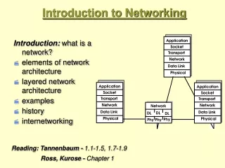
Under Code 367, Mr. Smith is guilty of larceny Lawyer Postal Service Airline Protocol Layers • Problem: Lawyers in different cities. • Layer specific functions, Headers
ISO/OSI Reference Model File transfer, Email, Remote Login Application 4 ASCII Text, Sound Presentation Establish/manage connection Session 3 End-to-end communication: TCP Transport Routing, Addressing: IP 2 Network Two party communication: Ethernet Datalink 1 How to transmit signal: Coding Physical
Transmission Media • Coaxial cable • Twisted Pair • Optical Fiber
Coaxial Cable • Used in original Ethernet ( 1983) Fig 2.20
Twisted Pair • Shielded Twisted Pair (STP)Used in original token ring • Unshielded Twisted Pair (UTP) • Category 1, 2, 3, …, 5, 6 • UTP-3: Voice Grade: Telephone wire • UTP-5: Data Grade: Better quality1 Mbps over 100 m in 1984 1000 Mbps over 100 m in 2002
Optical Fibers • Multimode Fiber: Core Diameter 50 or 62.5 mmWide core Þ Several rays (mode) enter the fiberEach mode travels a different distance • Single Mode Fiber: 10-mm core. Lower dispersion. Cladding Core
Fundamentals of Light l • Similar to waves produced by a stone throw in a pond • Frequency = Cycles per second at a point in space • Wavelength = Distance between peaks at time t • Speed = Frequency ×Wavelength • Speed in Vacuum = 300 m/ms • Speed in Fiber = 200 m/ms • Speed in Vacuum/Speed in Fiber 1.5 = Index of Refraction Amplitude Time or Space
1600 1500 1400 1300 1200 1100 1000 900 800 700 600 500 400 300 Fundamentals of Light (Cont) • Frequency of visible light 500 THz • Wavelength of visible light 600 nm(Violet = 400 nm, Red = 700 nm) • Visible light has a high lossÞ OK for short distance communication only • Infrared light (700-1600 nm) has a lower loss • Frequency of visible light 500 THz • Wavelength of visible light 600 nm(Violet = 400 nm, Red = 700 nm) • Visible light has a high lossÞ OK for short distance communication only • Infrared light (700-1600 nm) has a lower loss • Frequency of visible light 500 THz • Wavelength of visible light 600 nm(Violet = 400 nm, Red = 700 nm) • Visible light has a high lossÞ OK for short distance communication only • Infrared light (700-1600 nm) has a lower loss VisibleLight UltraViolet Optical Fiber Communication Infrared
Wavelength Division Multiplexing • 10 Mbps Ethernet (10Base-F) uses 850 nm • 100 Mbps Ethernet (100Base-FX) + FDDI use 1310 nm • Some telecommunication lines use 1550 nm • WDM: 850nm + 1310nm or 1310nm + 1550nm • Dense Þ Closely spaced 0.1 - 2 nm separation • Coarse = 2 to 25 nm = 4 to 12 l’s • Wide = Different Wavebands
Bitrate l Distance Recent DWDM Records • 32l× 5 Gbps to 9300 km (1998) • 16l× 10 Gbps to 6000 km (NTT’96) • 160l× 20 Gbps (NEC’00) • 128l× 40 Gbps to 300 km (Alcatel’00) • 64l× 40 Gbps to 4000 km (Lucent’02) • 19l× 160 Gbps (NTT’99) • 7l× 200 Gbps (NTT’97) • 1l×1200 Gbps to 70 km using TDM (NTT’00) • 1022 Wavelengths on one fiber (Lucent’99) Potential: 58 THz = 50 Tbps on 10,000 l’s Ref: IEEE J. on Selected Topics in Quantum Electronics, 11/2000.Optical Fiber Communications (OFC) Conference
Attenuation and Dispersion • Pulses become shorter and wider as they travel through the fiber
DeciBels Wire or Fiber • Power reduces exponentially with distance • Input = 10 mW, At 1 km: 5 mW, At 2 km: 2.5 mW, .. • Attenuation = Log10(Pin/Pout) Bel = 10 Log10(Pin/Pout) deciBel • Example: Pin = 10 mW, Pout= 5 mWAttenuation = 10 log10(10/5) = 10 log102 = 3 dB • Power is measured in dBm0 dBm = 1 mWn dBm = 10n/10 mW, 10log10x dBm = x mW • Example: Pin = 10 dBm, Pout = 7 dBm, Atten.= 3 dB
w1-D, w1, w2, w2+D D= w2 - w1 Four-Wave Mixing • If two signals travel in the same phase for a long time, new signals are generated.
l Product Gb/s km Avail- ’s ability Siemens/ Optisphere TransXpress 80 40 250 2001 160 10 250 2001 Alcatel 1640 OADM 160 2.5 2300 2001 80 10 330 2001 Corvis Optical Network Gateway 160 2.5 3200 2000 40 10 3200 2000 Ciena Multiwave CoreStream 160 10 1600 2001 Nortel Optera LH4000 56 10 4000 2000 Optera LH 5000 104 40 1200 2002 Sycamore SN10000 160 10 800 2001 40 10 4000 2001 Cisco ONS 15800 160 10 2000 2002 Recent Products Announcements • Ref: “Ultra everything,” Telephony, October 16, 2000
Physical Layer: Coding Bits 0 1 0 0 0 1 1 1 0 0 0 0 0 +5V • Simplest Coding: 0 = Light Off, 1 = Light OnNon-return to zero (NRZ) • Problems with NRZ: • Pulse width indeterminate: Clocking • DC, Baseline wander • No line state/error detection/Control signals NRZ -5V Clock Manchester NRZI
Bit, Baud, Hertz Pulse • Signal element: Pulse • Modulation Rate: 1/Duration of the smallest element =Baud rate • Data Rate: Bits per second • Frequency: Cycles per second = Hertz • Bit, Baud, Hertz: User, Receiver, Medium • Data Rate = Fn(Bandwidth, signal/noise ratio, encoding) +5V 0 -5V +5V 0 -5V Bit
Coding Examples 1 Second 14 b/s Bits 0 1 0 1 0 1 0 1 0 1 0 1 0 1 14 Baud, 7 Hz NRZ 14 b/s Bits 1 1 1 1 1 1 1 1 1 1 1 1 1 1 28 Baud, 14 Hz Manchester 14 b/s Bits 0 0 0 1 1 0 1 1 0 0 1 1 0 0 7 Baud, 3.5 Hz Multilevel
Layer 2: Datalink • Framing: Beginning and end of each message • Addressing: To whom if multiple receivers • Flow Control: To avoid buffer overflow at receiver • Error Control: Detect Errors, Ack each message, Retransmit if not acked 00110001000101010100110
High-Level Data Link Control • ISO Standard • Derived from Synchronous Data Link Control (SDLC): IBM • Mother of all datalinks • Link Access Procedure-Balanced (LAPB): X.25 • Link Access Procedure for the D channel (LAPD): ISDN • Link Access Procedure for modems (LAPM): V.42 • Point-to-Point Protocol (PPP): Internet
HDLC Framing • Flag: Indicates beginning and end of a frame = 01111110 • Address: Destination of the frame Ignored if point to point • Control: Type of frame (Data, Ack) Sequence number • Information: Message • Cyclic Redundancy Check (CRC): Detect errors Flag Address Control Information CRC Flag 1B 1B 1B 2B 1B Size
Bit Stuffing • Problem: What if user messages contain flag 01111110? • Patented Solution: Replace 11111 by 111110 at transmitterReplace all 111110 by 11111 at receiver Original Pattern 111111111111011111101111110 After bit-stuffing 1111101111101101111101011111010
Point-to-point Protocol (PPP) • Originally for User-network connectionNow being used for router-router connection • Typical connection setup: • Home PC Modem calls Internet Provider's router: sets up physical link • PC sends Link Control Protocol (LCP) packets • Select PPP (data link) parameters. Authenticate. • PC sends Network Control Protocol (NCP) packets • Select network parameters, E.g., Get IP address • Transfer IP packets
Info Padding CRC Flag PPP in HDLC-Like Framing • Flag = 0111 1110 = 7E • Byte Stuffing: 7E 7D 5E 7D 7D 5D • Address=FF Þ All stations. Control=03 Þ Unnumbered • 16-bit FCS default. 32-bit FCS can be negotiated using LCP Flag Address Control Protocol 01111110 11111111 00000011
CSMA/CD • Aloha at Univ of Hawaii: Transmit whenever you likeWorst case utilization = 1/(2e) =18% • Slotted Aloha: Fixed size transmission slotsWorst case utilization = 1/e = 37% • CSMA: Carrier Sense Multiple Access Listen before you transmit • CSMA/CD: CSMA with Collision DetectionListen while transmitting. Stop if you hear someone else
IEEE 802.3 CSMA/CD • If the medium is idle, transmit • If the medium is busy, wait until idle and then transmit immediately. • If a collision is detected while transmitting, • Transmit a jam signal for one slot(Slot = 51.2 s = 64 byte times) • Wait for a random time and reattempt (up to 16 times)Random time = Uniform[0,2min(k,10)-1] slots • Collision detected by monitoring the voltageHigh voltage two or more transmitters Collision Length of the cable is limited to 2 km
Ethernet Standards • 10BASE5: 10 Mb/s over coaxial cable (ThickWire) • 10BROAD36: 10 Mb/s over broadband cable, 3600 m max segments • 1BASE5: 1 Mb/s over 2 pairs of UTP • 10BASE2: 10 Mb/s over thin RG58 coaxial cable (ThinWire), 185 m max segments • 10BASE-T: 10 Mb/s over 2 pairs of UTP • 10BASE-FL: 10 Mb/s fiber optic point-to-point link • 10BASE-FB: 10 Mb/s fiber optic backbone (between repeaters). Also, known as synchronous Ethernet.
Ethernet Standards (Cont) • 10BASE-FP: 10 Mb/s fiber optic passive star + segments • 10BASE-F: 10BASE-FL, 10BASE-FB, or 10BASE-FP • 100BASE-T4: 100 Mb/s over 4 pairs of CAT-3, 4, 5 UTP • 100BASE-TX: 100 Mb/s over 2 pairs of CAT-5 UTP or STP • 100BASE-FX: 100 Mbps CSMA/CD over 2 optical fiber
Ethernet Standards (Cont) • 100BASE-X: 100BASE-TX or 100BASE-FX • 100BASE-T: 100BASE-T4, 100BASE-TX, or 100BASE-FX • 1000BASE-T: 1 Gbps (Gigabit Ethernet) 100BASE-T 100BASE-T4 100BASE-X 100BASE-TX 100BASE-FX
24 bits assigned by OUI Owner Organizationally Unique Identifier (OUI) Individual/Group Universal/Local 24 1 1 22 IEEE 802 Address Format • 48-bit:1000 0000 : 0000 0001 : 0100 0011 : 0000 0000 : 1000 0000 : 0000 1100 = 80:01:43:00:80:0C • Multicast = “To all bridges on this LAN” • Broadcast = “To all stations” = 111111....111 = FF:FF:FF:FF:FF:FF
Ethernet vs IEEE 802.3 IP IPX AppleTalk • Ethernet Dest.Address SourceAddress Type Info CRC Size in bytes 4 6 6 2 IP IPX AppleTalk • IEEE 802.3 Pad Dest.Address SourceAddress Length LLC Info CRC 6 6 2 Length 4
Extended LAN =Broadcast domain LAN= CollisionDomain B H H H H Router Gateway Router Bridge/Switch Repeater/Hub Interconnection Devices Application Application Transport Transport Network Network Datalink Datalink Physical Physical
Interconnection Devices • Repeater: PHY device that restores data and collision signals • Hub: Multiport repeater + fault detection and recovery • Bridge: Datalink layer device connecting two or more collision domains. MAC multicasts are propagated throughout “extended LAN.” • Router: Network layer device. IP, IPX, AppleTalk. Does not propagate MAC multicasts. • Switch: Multiport bridge with parallel paths • These are functions. Packaging varies.
Spanning Tree Fig 14.5
Spanning Tree (Cont) Fig 14.6
Spanning Tree Algorithm • All bridges multicast to “All bridges” • My ID • Root ID • My cost to root • The bridges update their info using Dijkstra’s algorithm and rebroadcast • Initially all bridges are roots but eventually converge to one root as they find out the lowest Bridge ID. • On each LAN, the bridge with minimum cost to the root becomes the Designated bridge • All ports of all non-designated bridges are blocked.
Bridge 1 Bridge 3 Bridge 4 Bridge 5 C=5 C=10 C=10 C=5 C=5 C=10 C=10 C=5 Spanning Tree Example LAN2 LAN5 LAN1 Bridge 2 C=10 C=5 C=5 LAN3 LAN4
Summary • ISO/OSI reference model has seven layers. • Physical layer deals with bit transmission across a single wire/fiber • Ethernet/IEEE 802.3 uses CSMA/CD. • Addresses: Local vs Global, Unicast vs Broadcast. • Spanning tree simple packet forwarding
Homework True or False? T F Datalink refers to the 2nd layer in the ISO/OSI reference model If you change UTP-5 with fiber based Ethernet, you have changed the physical layer UTP-3 is better than UTP-5 Multimode fiber has a thicker core than a single mode fiber and hence it is used for higher data rate transmission. A signal of100 mW power is transmitted. 1 mW is received after 50km attenuation is 2 dB/km It is impossible to send 3000 bits/second through a wire which has a bandwidth of 1000 Hz. Bit stuffing is used so that characters used for framing do not occur in the data part of the frame. Ethernet uses a CSMA/CD access method. 10Base2 runs at 2 Mbps. Spanning tree algorithm is used to find a loop free path in a network. Marks = Correct Answers _____ - Incorrect Answers _____ = ______