Download
1 / 78
780 likes | 954 Vues
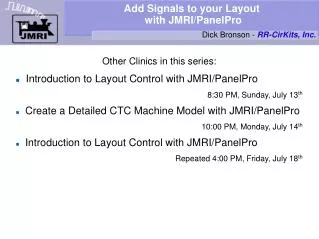
Add Signals to your Layout with JMRI/PanelPro. Dick Bronson - RR-CirKits, Inc. Other Clinics in this series: Introduction to Layout Control with JMRI/PanelPro 8:30 PM, Sunday, July 13 th Create a Detailed CTC Machine Model with JMRI/PanelPro 10:00 PM, Monday, July 14 th

E N D
Add Signals to your Layout with JMRI/PanelPro • Dick Bronson - RR-CirKits, Inc. Other Clinics in this series: • Introduction to Layout Control with JMRI/PanelPro 8:30 PM, Sunday, July 13th • Create a Detailed CTC Machine Model with JMRI/PanelPro 10:00 PM, Monday, July 14th • Introduction to Layout Control with JMRI/PanelPro Repeated 4:00 PM, Friday, July 18th
SSL (Simple Signal Logic) • SSL is the PanelPro name for ABS signaling. • According to Wikipedia Automatic Block Signal, or ABS, systems consist of a series of signals that govern blocks of track between the signals. The signals are automatically activated by the conditions of the block beyond the signal. Signals in ABS territory do not denote occupancy. Signals in ABS territory are set up to denote the most restricted indication. ... Train crews that operate in ABS, often operate with track warrants or traffic control. • Only CTC systems are considered sufficient authority to run trains based strictly on signal indications. This is because CTC signals default to 'Stop' and require a dispatcher to 'Clear' them.
SSL (Simple Signal Logic) • SSL basics • ABS defaults to 'Clear' signals, and drops to 'Stop' if the block immediately beyond the signal is occupied, or if the switch (turnout) beyond the signal is set against the direction of traffic.
SSL (Simple Signal Logic) • SSL basics • ABS defaults to 'Clear' signals, and drops to 'Stop' if the block immediately beyond the signal is occupied, or if the switch (turnout) beyond the signal is set against the direction of traffic. • Therefore ABS requires input information for track occupancy and for switch position.
SSL (Simple Signal Logic) • SSL basics • ABS defaults to 'Clear' signals, and drops to 'Stop' if the block immediately beyond the signal is occupied, or if the switch (turnout) beyond the signal is set against the direction of traffic. • Therefore ABS requires input information for track occupancy and for switch position. • ABS also shows a limited speed indication called 'Approach' if the next signal beyond this signal is showing 'Stop'. This is a warning to the train crew to approach the next signal prepared to 'Stop' before they reach it.
SSL (Simple Signal Logic) • SSL basics • ABS defaults to 'Clear' signals, and drops to 'Stop' if the block immediately beyond the signal is occupied, or if the switch (turnout) beyond the signal is set against the direction of traffic. • Therefore ABS requires input information for track occupancy and for switch position. • ABS also shows a limited speed indication called 'Approach' if the next signal beyond this signal is showing 'Stop'. This is a warning to the train crew to approach the next signal prepared to 'Stop' before they reach it. • If the signals are close, or trains long, some systems would give a double warning using a flashing signal.
SSL (Simple Signal Logic) • SSL basics • In some cases a signal at the block boundry may not be visible due to terrain, tunnels, buildings, etc. In that case a slave or 'Distant' signal could be used as a 'heads up'. In SSL checking the 'Is Distant Signal' will tie a signal to the next (Protected) signal and show the most restrictive setting of either signal. • Approach Lighting. In the earlier days of signaling it was common to have signals turn out their lamps if there were no trains approaching them in order to save lamp life and battery power. Now that most signals are utility powered this is less common. Most modelers ignore this feature because a series of dark signals is not very interesting to onlookers.
SSL (Simple Signal Logic) • SSL basics • Re-open our new SSL-Clinic-2 panel.
SSL (Simple Signal Logic) • SSL basics • Re-open our new SSL-Clinic-2 panel. • We already have occupancy sensors for our OS sections.
SSL (Simple Signal Logic) • SSL basics • Re-open our new SSL-Clinic-2 panel. • We already have occupancy sensors for our OS sections. • The US&S default was white jewels for track other than the OS. We will do the same. If your RR used some other color, do so by choosing different colors for your images.
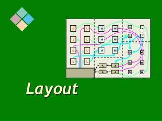
SSL (Simple Signal Logic) • SSL basics • Position each new sensor image where appropriate.
SSL (Simple Signal Logic) • SSL basics • Position each new sensor image where appropriate. • We now have sufficient information from the layout to add our signals. (occupancy plus switches)
SSL (Simple Signal Logic) • SSL basics • Position each new sensor image where appropriate. • We now have sufficient information from the layout to add our signals. (occupancy plus switches) • Actually an ABS system would not have a central panel like we are creating here. We are only making the panel to more easily understand the way the JMRI system operates.
SSL (Simple Signal Logic) • Signal head basics • Go to the PanelPro window and select 'tools'.
SSL (Simple Signal Logic) • Signal head basics • Go to the PanelPro window and select 'tools'. • Navigate to 'Tables' – 'Signals' and click to open the 'Signal Table'.
SSL (Simple Signal Logic) • Signal head basics • Go to the PanelPro window and select 'tools'. • Navigate to 'Tables' – 'Signals' and click to open the 'Signal Table'. • Click 'Add ...' to add new signal heads.
SSL (Simple Signal Logic) • Signal head basics • Go to the PanelPro window and select 'tools'. • Navigate to 'Tables' – 'Signals' and click to open the 'Signal Table'. • Click 'Add ...' to add new signal heads. • This brings up a new window requesting specifics on the hardware.
SSL (Simple Signal Logic) • Signal head basics • Go to the PanelPro window and select 'tools'. • Navigate to 'Tables' – 'Signals' and click to open the 'Signal Table'. • Click 'Add ...' to add new signal heads. • This brings up a new window requesting specifics on the hardware. • There are different basic hardware choices, each with its own details.
SSL (Simple Signal Logic) • Signal head basics • Triple Output. This refers to a signal that has individual drivers for each output. Originally this was called 'Triple Turnout' because many systems use 'turnouts' as general purpose output devices.
SSL (Simple Signal Logic) • Signal head basics • Triple Output. This refers to a signal that has individual drivers for each output. Originally this was called 'Triple Turnout' because many systems use 'turnouts' as general purpose output devices. • This ID is the system type plus ”H” for 'signal Head'. For example 'LH' for Digitrax LocoNet devices. • Individual output lines get entered here. (e.g. LT25)
SSL (Simple Signal Logic) • Signal head basics • Double Output. This refers to a signal that has two drivers. This implies some sort of decoding in the hardware or visually. (for example driving a red plus a green searchlight LED at the same time will produce a yellow signal)
SSL (Simple Signal Logic) • Signal head basics • Double Output. This refers to a signal that has two drivers. This implies some sort of decoding in the hardware or visually. (for example driving a red plus a green searchlight LED at the same time will produce a yellow signal) • The system name and hardware ID are similar to the triple output head.
SSL (Simple Signal Logic) • Signal head basics • Virtual. This refers to a signal that has no actual hardware on the layout. Sometimes it is convienient to use a virtual signal to fill in the 'details', so to speak, and then use the 'Distant' option to include the 'details' into another actual signal's indication. It is not even necessary to include the virtual signal on the panel.
SSL (Simple Signal Logic) • Signal head basics • SE8c 4 Aspect. The SE8c is Digitrax's signal driver board. Our TC-64 board will also operate in SE8c (signal) mode. The SE8c mode just sends out single commands for each aspect change, which saves some bandwidth on the network. (a relatively minor amount)
SSL (Simple Signal Logic) • Signal head basics • LDT LS-DEC. Littfinski Daten Technik Light Signal Decoder. This signal decoder has different versions that directly support many of the complex european multi-head signal systems.
SSL (Simple Signal Logic) • Signal head basics • DCC Signal Decoder. This signal type controls signal heads attached to any decoder that uses the DCC signal packets as defined by the NMRA DCC Working Group.
SSL (Simple Signal Logic) • Signal head basics • DCC Signal Decoder. This signal type controls signal heads attached to any decoder that uses the DCC signal packets as defined by the NMRA DCC Working Group. • Enter its DCC address as the system number.
SSL (Simple Signal Logic) • Signal head basics • Our example is using the 'LocoNet Simulator' or TC-64 with encoding, so select 'Double Output'.
SSL (Simple Signal Logic) • Signal head basics • Our example is using the 'LocoNet Simulator' or TC-64 with encoding, so select 'Double Output'. • My searchlight signals are wired opposite to this, so line 1 is red, line 2 is green etc.
SSL (Simple Signal Logic) • Signal head basics • Our example is using the 'LocoNet Simulator' or TC-64 with encoding, so select 'Double Output'. • My searchlight signals are wired opposite to this, so line 1 is red, line 2 is green etc. • The TC-64 signal port base address is 16, so the output lines start with LT17, LT18, etc. (port address plus line number)
SSL (Simple Signal Logic) • Signal head basics • Our example is using the 'LocoNet Simulator' or TC-64 with encoding, so select 'Double Output'. • My searchlight signals are wired opposite to this, so line 1 is red, line 2 is green etc. • The TC-64 signal port base address is 16, so the output lines start with LT17, LT18, etc. (port address plus line number) • Click 'OK' to add a signal.
SSL (Simple Signal Logic) • Signal head basics • Once the signal head is in the Signal Table, add a description to match it. I called it 'Plant 6 Facing Diverging', but you could name it any way that seems good for your RR.
SSL (Simple Signal Logic) • Signal head basics • Once the signal head is in the Signal Table, add a description to match it. I called it 'Plant 6 Facing Diverging', but you could name it any way that seems good for your RR. • A good thing to do at this point is to see if your hardware responds as expected. Clicking on the 'State' button should cycle the actual signal through its various aspects.
SSL (Simple Signal Logic) • Signal head basics • Once the first signal head is working correctly, add in the rest of them.
SSL (Simple Signal Logic) • Signal head basics • Once the first signal head is working correctly, add in the rest of them. • This would be a good time to save your work again.
SSL (Simple Signal Logic) • Signal head basics • Once the first signal head is working correctly, add in the rest of them. • This would be a good time to save your work again. • For this session of the clinic we will add signal images to the panel to help us visualize what is happening. For a prototypical panel we would skip this step. • Drill down to searchlights.
SSL (Simple Signal Logic) • Signal head basics • Dig through the various images to get a set of short signals with white backgrounds. (that show up OK on our black panel)
SSL (Simple Signal Logic) • Signal head basics • Dig through the various images to get a set of short signals with white backgrounds. (that show up OK on our black panel) • Enter the first head. (LH1) 'Facing Diverging' will be the lower signal of 2 heads.
SSL (Simple Signal Logic) • Signal head basics • Dig through the various images to get a set of short signals with white backgrounds. (that show up OK on our black panel) • Enter the first head. (LH1) 'Facing Diverging' will be the lower signal of 2 heads. • Move the signal into position.
SSL (Simple Signal Logic) • Signal head basics • Dig through the various images to get a set of short signals with white backgrounds. (that show up OK on our black panel) • Enter the first head. (LH1) 'Facing Diverging' will be the lower signal of 2 heads. • Move the signal into position. • Add the second head and place it above the first one.
SSL (Simple Signal Logic) • Signal head basics • Dig through the various images to get a set of short signals with white backgrounds. (that show up OK on our black panel) • Enter the first head. (LH1) 'Facing Diverging' will be the lower signal of 2 heads. • Move the signal into position. • Add the second head and place it above the first one. • #3 and #4 need rotating.
SSL (Simple Signal Logic) • Signal head basics • Continue to place your signals, rotating them as required.
SSL (Simple Signal Logic) • Signal head basics • Continue to place your signals, rotating them as required. • Clicking on the images will change the signals on your layout. This allows you to easily check your locations.
SSL (Simple Signal Logic) • Signal head basics • Continue to place your signals, rotating them as required. • Clicking on the images will change the signals on your layout. This allows you to easily check your locations. • This is another good point to save your work.
SSL (Simple Signal Logic) • Signal Logic • Continue to place your signals, rotating them as required. • Clicking on the images will change the signals on your layout. This allows you to easily check your locations. • This is another good point to save your work. • The easiest way to open up the SSL for each signal head is to simply right click on the image and select 'Edit Logic',
SSL (Simple Signal Logic) • Signal Logic • This automatically brings up the SSL edit window for the selected signal head. • First select the proper mode for this signal head.
SSL (Simple Signal Logic) • Signal Logic • This automatically brings up the SSL edit window for the selected signal head. • First select the proper mode for this signal head. • There is pop up help for virtually every item in the SSL editor to help you understand the function of each item. Simply pause your mouse over the item in question.
SSL (Simple Signal Logic) • Signal Logic • This automatically brings up the SSL edit window for the selected signal head. • First select the proper mode for this signal head. • There is pop up help for virtually every item in the SSL editor to help you understand the function of each item. Simply pause your mouse over the item in question. • This is the diverging leg.
SSL (Simple Signal Logic) • Signal Logic • Do NOT choose 'On Facing-Point Turnout' unless you just have a single head controlling both routes.
SSL (Simple Signal Logic) • Signal Logic • Do NOT choose 'On Facing-Point Turnout' unless you just have a single head controlling both routes. • 'Protects' means that a signal goes to 'stop' in front of these sensors when they are active. I.e. It is the track that is being protected from any train that might be entering it.