2D TO 3D MODELLING
KCCOE PROJECT PRESENTATION. 2D TO 3D MODELLING. Submitted by ---. Student: Ashish Nikam Ashish Singh Samir Gaykar Sanoj Singh Guidence: Prof. Ashwini Jaywant. INTROUCTION. 3D models are obtained from 2D views.

2D TO 3D MODELLING
E N D
Presentation Transcript
KCCOE PROJECT PRESENTATION 2D TO 3D MODELLING Submitted by --- Student: Ashish Nikam Ashish Singh Samir Gaykar Sanoj Singh Guidence: Prof. Ashwini Jaywant
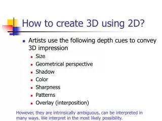
INTROUCTION • 3D models are obtained from 2D views. • 2D images which are scanned using laser are captured using webcam which determines depth of each pixel and then this image is converted into surface image. • The processed images are then placed on the visual platform thus giving us a 3D model of the object that was captured by the camera.
EXISTING METHOD FOR 3D MODELLING Time-of-flight Laser rangefinder: distance to the first object on its path is measured. Laser: emits a pulse of light. Detector: reflected light is seen. Timing the round-trip time of a pulse of light. Stereoscopic Human stereoscopic vision based. Two video cameras are arranged. Differences between the images seen by each camera. Determine the distance at each point in the images. Triangulation Laser on the object A camera looks for the location of the laser dot. Laser dot, camera and laser emitter form a triangle. Photometric Single camera Multiple images under varying lighting conditions. Surface orientation at each pixel. Silhouette Photos are taken around an object against a background. Outlines created from a sequence of photos. Silhouettes are extruded and intersected. Visual hull approximation of the object. Some concavities are not detected. Handheld Laser A laser dot or line is projected onto an object. Handheld laser device and a sensor is applied. Position of the scanner is recorded (laser tracker).
OUR APPROACH • This project aims at providing a 3D image using nothing more than a simple image capturing device [a high resolution webcam] and a rotating platform on which the object is mounted. The rotation of this platform is to be controlled by a microcontroller and a stepper motor. The rotation occurs in discrete steps which are programmed at the micro controller. The resolution of the 3D image depends on the number of images which are used to reconstruct it. Therefore the degree of rotation is a control for the 3D image resolution. • Once the images are captured they have to be stored sequentially on the computer using the USB interface. The webcam image capture is closely synchronized with the rotation of the platform so that the image is captured at the exact moment when the platform is stationary. The images from different angles are then used to reconstruct a 3D image. Image stitching algorithms perform this task. • The proposed project is an attempt at providing a low cost portable alternative to the existing techniques that provide similar results. Special attention has been paid to reduce the tradeoff between details and the time required thus satisfying a wide spectrum of needs.
HARDWARE & SOFTWARE • Computer • Microcontroller (89C51) • Stepper motor and motor controller (ULN2003) • RS232 cable • Webcam • MATLAB Software based image processing using laser scanning
BLOCK DIAGRAM MICROCONTROLLER MOTOR CONTROLLER (ATMEGA 8) SERVO MOTOR (ULN2003) RS232 CAMERA
Object Laser (x,y) Camera OPERATION: EDGE DETECTION Figure 2 • A camera looks for the location of the laser dot. • Laser dot, camera and laser emitter form a triangle Figure 1
CANNY EDGE DETECTION 1. smooth 2. gradient 3. thresh, suppress, link Edge is Where Change Occurs
THE CANNY EDGE DETECTOR 1: Original Image (Lena) 2: Norm Of The Gradient 4: Thinning (Non-maximum Suppression) 3: Thresholding
FINAL IMPLENEMTATION Reconstructed 3D image
ADVANTAGES & APPLICATIONS • The medical industry uses detailed models of organs. • The movie industry uses them as characters and objects for animated and real-life motion pictures. • The video game industry uses them as assets for computer and video games. • The science sector uses them as highly detailed models of chemical compounds. • The architecture industry uses them to demonstrate proposed buildings and landscapes through Software Architectural Models. • The engineering community uses them as designs of new devices, vehicles and structures as well as a host of other uses. • In recent decades the earth science community has started to construct 3D geological models as a standard practice.
FUTURE SCOPE • Replacing the turntable with an improved model. • Increasing the laser fan angle from 60. • Replacing the camera with one that allows for turning automatic gain off. • Reduce noise and blooming. • Improve image acquisition and processing software user interface.
REFERENCES • http://en.wikipedia.org/wiki/3D_scanner • http://courses.cit.cornell.edu/ee476/FinalProjects/s2009/dat38/Website/index.htm • http://www.owlnet.rice.edu/~elec539/Projects97/morphjrks/laplacian.html • http://sites.google.com/site/elsamuko/gimp/gimp-octave