
Diode :- Clamper
E N D
Presentation Transcript
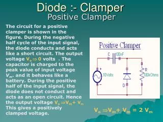
The circuit for a positive clamper is shown in the figure. During the negative half cycle of the input signal, the diode conducts and acts like a short circuit. The output voltage Vo 0 volts . The capacitor is charged to the peak value of input voltage Vm. and it behaves like a battery. During the positive half of the input signal, the diode does not conduct andacts as an open circuit. Hence the output voltage Vo Vm+ Vm This gives a positively clamped voltage. Diode :- Clamper Positive Clamper VoVm+ Vm = 2 Vm
Diode :- Clamper Positive Clamper
Diode :- Clamper During the positive half cycle the diode conducts and acts like a short circuit. The capacitor charges to peak value of input voltage Vm. During this interval the output Vo which is taken across the short circuit will be zero During the negative half cycle, the diode is open. The output voltage can be found by applying KVL. Negative Clamper
Diode :- Clamper Negative Clamper
Diode :- Clamper Biased Clamper
Diode :- Clamper The circuit of a positively biased clamper is shown in the figure. During the negative half cycle of the input signal the diode is forward biased and acts like a short circuit. The capacitor charges to Vi + Vs . Applying the KVL to the input side During the positive half cycle of the input signal, the diode is reverse biased and it acts as an open circuit. Hence Vs has no effect on Vo. Applying KVL around the outside loop.
Clippers CLIPPERS AND LIMITERS
Clipping removes part of the positive or negative peaks of a signal or both. Silicon diodes do not conduct until the applied voltage exceeds about 0.6 volts and only when the anode is positive with respect to the cathode. • The circuit is like a potential divider with the diode part being high resistance for voltages below 0.6 volts and low resistance above.