Diodes
Diodes. 1. Diode. Class of non-linear circuits having non-linear v-i Characteristics Uses Generation of : DC voltage from the ac power supply Different wave (square wave, pulse) form generation Protection Circuits Digital logic & memory circuits. Creating a Diode.


Diodes
E N D
Presentation Transcript
Diodes 1
Diode • Class of non-linear circuits • having non-linear v-i Characteristics • Uses • Generation of : • DC voltage from the ac power supply • Different wave (square wave, pulse) form generation • Protection Circuits • Digital logic & memory circuits
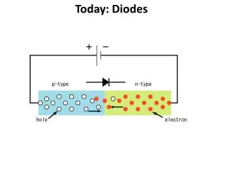
Creating a Diode • A diode allows current to flow in one direction but not the other. • When you put N-type and P-type silicon together gives a diode its unique properties.
Diode Equivalent circuit in the reverse direction Equivalent circuit in the forward direction.
Operation Reverse Bias • -ve voltage is applied to Anode • Current through diode = 0 (cut off operation) • Diode act as open circuit Forward Bias +ve voltage applied to Anode • Current flows through diode • voltage Drop is zero (Turned on) • Diode is short circuit
The two modes of operation of ideal diodes Reverse biased Reverse Voltage 10 V Forward biased Forward Current 10 mA
Rectifier circuit Input waveform Equivalent circuit when vi0 Output waveform. Equivalent circuit when vi≤ 0 Waveform across diode
Diodes are ideal , Find the value of I and V Figure 3.6 Circuits for Example 3.2.
Example 3.2. Assumption Both Diodes are conducting
Assumption Both Diodes are conducting Node A Node B Not Possible Thus assumption of both diode conducting is wrong
Example 3.2(b). Assumption # 2 Diodes 1 is not conducting Diodes 2 is conducting Assumption is correct
Figure E3.4 Diodes are ideal , Find the value of I and V
Figure E3.4 Diodes are ideal , Find the value of I and V I= 2mA V= 0V I= 0A V= 5V I= 0A V= -5V I= 2mA V= 0V
Figure E3.4 Diodes are ideal , Find the value of I and V I= 3mA V= 3V I= 4mA V= 1V
Diodes are ideal , Find the value of I and V Figure P3.2
Figure P3.2Diodes are ideal , Find the value of I and V Diode is conducting I = 0.6 mA V = -3V Diode is cut-off I = 0 mA V = 3V Diode is conducting I = 0.6 mA V = 3V Diode is cut-off I = 0 mA V = -3V
Problem 3-3 Diodes are ideal , Find the value of I and V D1 Cut-Off & D2 Conducting I = 3mA D1 Cut-Off & D2 Conducting I = 1mA , V=1 V
Figure P3.4 In ideal diodes circuits, v1is a 1-kHz, 10V peak sine wave. Sketch the waveform ofvo
In ideal diodes circuits, v1is a 1-kHz, 10V peak sine wave. Sketch the waveform ofvo Vp+ = 10V Vp- = 0V f = 1 K-Hz Vp+ = 0V Vp- = - 10V f = 1 K-Hz Vo = 0V
Figure P3.4 In ideal diodes circuits, v1s a 1-kHz, 10V peak sine wave. Sketch the waveform ofvo Vp+ = 10V Vp- = -10V f = 1 K-Hz Vp+ = 10V Vp- = 0V f = 1 K-Hz Vp+ = 10V Vp- = 0V f = 1 K-Hz
Figure P3.4 In ideal diodes circuits, v1s a 1-kHz, 10V peak sine wave. Sketch the waveform ofvo
Figure P3.4 In ideal diodes circuits, v1s a 1-kHz, 10V peak sine wave. Sketch the waveform ofvo Vp+ = 0V Vp- = -10V f = 1 K-Hz V0 = 0V Vp+ = 10V Vp- = -5V f = 1 K-Hz
Figure P3.4 In ideal diodes circuits, v1s a 1-kHz, 10V peak sine wave. Sketch the waveform ofvo Vp+ = 10V Vp- = -5V f = 1 K-Hz
Problem 3-4(k) For Vi >0 V D1 is cutoff D2 is conducting vo=1V For Vi < 0 V is conducting D2 is cutoff vo=vi+1V - 9 V
Figure P3.6 X = A . B X = A + B
Problem 3-4 (c) vo=zero
Problem 3-4(f) Vi is a 1kHz 10-V peak sine wave. +ve Half Cycle with 10 V peak at 1 KHz
Problem 3-4(h) vo=zero
Problem 3.5 vi is 10 V peak sine wave and I = 100 mA current source. B is battery of 4.5 V . Sketch and label the iB 100 mA 4.5 v
Solution P3-5 100 mA vo 4.5 v
Problem 3-5 100 mA 4.5 v
Problem 3-5 10 4.5 100 mA
REVERSE POLARITY PROTECTOR • The diode in this circuit protects a radio or a recorder etc... In the event that the battery or power source is connected the wrong way round, the diode does not allow current to flow.
I1 2 I3 Problem 3-9 I1 2 I3 D1& D2 Conducting I1=1mA I3=0.5 mA I2=0.5 mA V= 0 V D1=off, D2=On I1= I3=0.66 mA V = -1.7 V
Problem 3-10 D conducting I=0.225 mA V=4.5V D is not conducting I=0A V=-2V
Problem 3-16 V REDGREEN 3V On Off D1 conducts 0 V Off Off -3 V Off On D2 conducts
Quiz No 3 DE 28 EE -A Sketch vO if vi is 8 sin Find out the conduction angle for the diode & fraction of the cycle the diode is conducting
8V I1 I2 I Solution Quiz No 3 vi/2 10-10-07
Sketch vO if vi is 10 sin Find out the conduction angle for the diode & fraction of the cycle the diode is conducts +12 V D1 never conducts Vi<5V D2 is cut-off, Vo=5V Vi>5V D2 is conducts D1 D2 5 22-10-07
Quiz No 3 DE 27 CE -B Sketch vO if vi is 10 sin Find out the conduction angle for the diode & fraction of the cycle the diode is conducts D1 never conducts Vi<5V D2 is cut-off, Vo=Vi Vi>5V D2 is conducts
Problem • Assume the diodes are ideal, sketch vo if the input is 10sin (9) • Find out the conduction angles for Diode D1 & D2 (4) and the fraction of the cycle these diodes conduct. (2)