Diodes
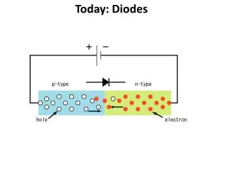
Diodes. 1 . Basic diode concept. 2 . Load-line analysis of diode circuit. 3 . Zener-diode voltage regulator circuit. 4 . Ideal-diode model. 5 . Applications of diodes. BASIC DIODE CONCEPTS. A pn junction. Drift and diffusion currents in a pn junction. Figure 9.7.


Diodes
E N D
Presentation Transcript
Diodes 1. Basic diode concept. 2. Load-line analysis of diode circuit. 3. Zener-diode voltage regulator circuit. 4. Ideal-diode model. 5. Applications of diodes.
Figure 9.7 Forward- and reverse-biased pn junctions
Figure 9.8, 9.9 Semiconductor diode i-v characteristic Semiconductor diode circuit symbol
Figure 9.10 The i-v characteristic of the semiconductor diode
Shockley Equation k = 1.38 × 10⁻²³ J/K is Boltzmann’s constant and q = 1.60 × 10⁻¹⁹ C is the magnitude of the electrical charge of an electron. At a temperature of 300 K, we have
Exercise 10.1At a temperature of 300K, a certain junction diode has iD = 0.1mA for vD = 0.6V. Assume that n is unity and use VT = 0.026V. find the value of the saturation current Is.
LOAD-LINE ANALYSIS OF DIODE CIRCUITS By applying KVL, we get But two unknowns, we need one more equation relating iD and vD to solve the problem.
Example 10.1If the circuit of Figure 10.5 has Vss = 2V, R = 1kW, and a diode with the characteristic shown in Figure 10.7, find the diode voltage and current at the operating point.Example 10.2Repeat Example 10.1 if Vss = 10V, R = 10kW
Vss = i R + VD Vss = 2, R = 1k Vss=10, R=10k
Zener Diodes Diodes that are intended to operate in the breakdown region are called Zener diodes.
ZENER-DIODE VOLTAGE-REGULATOR CIRCUITS A voltage regulator circuit provides a nearly constant voltage to a load from a variable source.
Example 10.3The voltage-regulator circuit of Figure 10.9 has R = 1kW and use a Zener diode having the characteristic shown in Figure 10.10. Find the output voltage for Vss = 15V. Repeat for Vss = 20V.
R = 1k Vss + i R +VD = 0 i = 0, VD = -Vss VD = 0, i = Vss/R
IDEAL-DIODE MODEL The ideal diode acts as a short circuit for forward currents and as an open circuit with reverse voltage applied.
Figure 9.11 Large-signal on/off diode model
Figure 9.12, 9.13, 9.14 Circuit containing ideal diode Circuit of Figure 9.12, assuming that the ideal diode conducts Figure 9.13 Circuit of Figure 9.12, assuming that the ideal diode does not conduct Figure 9.14
Figure 9.15, 9.16, 9.17 Figure 9.16 Figure 9.17
Figure 9.45 DC power supply
Figure 9.20, 9.21 Ideal diode rectifier input and output voltages
Figure 9.42 Operation of bridge rectifier
Figure 9.49 • A Zener diode voltage regulator; • (b) simplified circuit for Zener regulator