Download
1 / 13
130 likes | 303 Vues
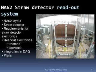
NA62 straw readout. Characterization and qualification of the frontend electronics Detector and interface to frontend Small readout system Plans Expected activities till December 2010 and for the next year. Characterization and qualification of the frontend electronics. Situation

E N D
NA62 straw readout • Characterization and qualification of the frontend electronics • Detector and interface to frontend • Small readout system • Plans • Expected activities till December 2010 and for the next year
Characterization and qualification of the frontend electronics • Situation • Good quality on time measurement for both leading and trailing edges is crucial for event building, analysis and eventual trigger/veto • CARIOCA • Ongoing characterization of the chip • From lab and test beam measurements, 1 -7 pulses on single particle depending on gas • Waiting for analysis from test beam • Frontend board (cover) with 1 bug (reverted output polarity on one chip) • Not serious for test beam • Will be fixed in the next version • At the moment all indicates good quality of system design, if decided to go this way we need only small modifications • GASII • Ongoing characterization of the chip • Not yet connected to straw • Test bench measurements show good performance • Slightly longer shaping can help with multiple pulses • Characterization and test with straws must be finished before December • Production plan not yet fixed
Characterization and qualification of the frontend electronics • Discrete electronics • Reason • Possibility to tune shaping (avoid multiple pulses on single particle, optimize performance) • Possibility to use constant-fraction discri if needed • Differential input to improve S/N and suppress crosstalk • status • Design and simulation finished • 4 channel functional and dimensional demonstrator • 1 channel needs ~10mm strip • PCB designed and going to production • Crucial components already delivered
Characterization and qualification of the frontend electronics
Time jitter • What parameters for time measurements? • If only noise from electronics, optimum peaking time is ~8*t0 for point-like ionization • Due to noise from the detector and components around, and due to electron arrival time fluctuation, the good compromise is considered ~(4-6)*t0 • T0 for Ar:CO2 is ~2.3ns, BUT, close to wire (firsts 10nth of ns) it is rather 2-3 times higher due to ion non-linear mobility • T0 which matters for timing (2-3)*2.3ns ~ 5ns • So, peaking time should be (4-6)*5ns = 20ns-30ns (CARIOCA ~12ns, GASII ~17ns, discrete tunable) • Jitter of FE alone • CARIOCA done (Johan) • GASII done (Johan) • Discrete when produced • ‘real’ time jitter is entirely determined by • Noise from the detector • System noise • Signal formation in the straw
Time jitter • CARIOCA and GASII tested with • Delta charge (step voltage over 1.8pF capacitor) • Simulated point-like ionization for t0 = 1ns, 2.5ns, 5ns • Signal to noise ratio = 10
Time jitter CARIOCA • Results • Delta • 49 ps leading edge • 61 ps trailing edge • T0 = 1 ns • 61ps leading edge • 170 ps trailing edge • T0 = 2.5 ns • 63ps leading edge • 267pstrailing edge • T0 = 5 ns • 66ps leading edge • 417ps trailing edge
Time jitter GASII • Results • Delta • 158 ps leading edge • 257ps trailing edge • T0 = 1 ns • 218ps leading edge • 402ps trailing edge • T0 = 2.5 ns • 221ps leading edge • 365 ps trailing edge • T0 = 5 ns • 241ps leading edge • 405ps trailing edge
Detector and interface to frontend • Web circuit • Big sensitivity observed • Placement • Distance from straw pin • length • Crosstalk • Waiting for test beam results • Test in lab with injected signals and cosmics • Noise and sensitivity • Waiting for test beam results • Tests in lab (characterization) of chips • Tests with cosmics and Fe55
Small readout system • Design started • 6U VME board • Serving 4 SCSI cables with present covers • Serving 4 ethernet cables with new frontend (TDC on cover) • Readout and control over VME backplane • Design service at CERN prepared to do the layout and production ASAP • Technical student expected to take a significant role in design, testing and debugging
Plans • For the readout of the first chamber next year and common testbeam we have to • Finish characterization and tests of various frontend electronics in December • Finish characterization and tests of detector interface and grounding and shielding in December • Take decision in Dec/Jan on frontend and detector • Develop and construct small readout system (demonstrator) in 2010 • For the testbeam 2011 we can maybe use small readout • Study of readout (backend) boards including TELL1 can continue in 2011 • (Wo)man power • Myself 70% • Borrowed technician from ESE/ME group till …? • Technical student from 1.10.2010
Expected activities till December 2010 • Frontend • Characterization of CARIOCA and GASII • Discrete frontend • Results from testbeam • Detector interface • Web circuit • Crosstalk • Noise • Prototype of readout system • Readout for 4 covers (fe boards) for different versions • Qualification of the connectivity (SCSI or ethernet) • Ordering of cables (depends on previous) • Last two can happen in january 2011 as also depends on final backend
Expected activities in 2011 • Frontend • Decision on the analog (CARIOCA,PENN, DISCRETE) • Design and test of preproduction version • Design (if needed) and production of final version for 1 chamber • Develop procedure and electronics for testing and debugging for serial production • Define required tests and procedures • Injector board and readout • Software • Backend • Design and production of preproduction readout (SRB or TELL1) • Design (if needed) and production of final readout for 1 chamber • Develop procedure and electronics for testing and debugging for serial production • Test beam with one chamber with final electronics