Download
1 / 16
160 likes | 260 Vues
Explore cutting-edge sub-ps event timing technology advancements - novel timing principle, new electronics technologies, field test results, and future optical event timing vision.

E N D
Progress in sub-picosecond event timing Ivan Prochazka* , Petr Panek presented at 16th International Workshop on Laser Ranging Poznan, Poland, October 13-17, 2008 * Czech Technical University in Prague Institute of Photonics and Electronics, Academy of Sciences of the Czech Republic, Prague, Czech Republic
Outline • Novel timing principle of sub-ps event timing • New technologies in electronics(SiGe ultrafast logic, “no ground”, SAW filters,..) • First device design and construction • Timing results : jitter, linearity, stability • First field test results I.Prochazka, P.Panek, 16th Worksho on Laser Ranging, Poznan, Poland, Oct. 2008
New timing principle theory by Petr Panek US Patent, 2005 • Time measurement is carried out in a FREQUENCY DOMAIN • The time-interpolation by the SAW filter • The SAW filter output synchronously sampled & digitized • Time / epoch is computed using the reverse FFT I.Prochazka, P.Panek, 16th Worksho on Laser Ranging, Poznan, Poland, Oct. 2008
New technologies employed • Ultrafast SiGe 10 GHz logic 35 ps slopes 50 Ohms lines matched drift ~ 0.5 ps / K • logical gain 1 high costs, limited availability PCB design, soldering problems • SAW filters used as time interpolators • 200 MHz Module, J.Kolbl and P.Sperber,Deggendorf, 2005 extreme spectral purity • Circuit design complementary signals only = > “NO GROUND” maximum design symetry ~ 10 ps delay matched cables I.Prochazka, P.Panek, 16th Worksho on Laser Ranging, Poznan, Poland, Oct. 2008
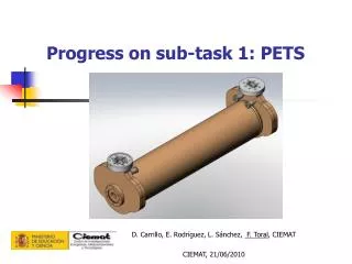
First sample construction Power supply SAW filter Exciter Sampler & A/Ddata interface Interpolator based on SAW filter I.Prochazka, P.Panek, 16th Worksho on Laser Ranging, Poznan, Poland, Oct. 2008
Device operational test – full configuration I.Prochazka, P.Panek, 16th Worksho on Laser Ranging, Poznan, Poland, Oct. 2008
Timing jitter - cable delay test Jitter per channel ~ 920 fs, normal distribution Review of Scientific Instruments, 78,1 (2007) I.Prochazka, P.Panek, 16th Worksho on Laser Ranging, Poznan, Poland, Oct. 2008
Timing linearity - the worst case phase 21st harmonics Amplitude 0.7 ps Reproducible, may be SW modeledjust 2 parameters fit (amplitude, phase) I.Prochazka, P.Panek, 16th Worksho on Laser Ranging, Poznan, Poland, Oct. 2008
Timing linearity – dependence on Tb-Ta phase Mean 0.42 ps for 2 channels worst case No sw corrections best case I.Prochazka, P.Panek, 16th Worksho on Laser Ranging, Poznan, Poland, Oct. 2008
Temperature drift (Tb-Ta), channel to channel Drift -8.6 fs / hour Ambient temperature stable +/- 0.5 C 3 hours / screen I.Prochazka, P.Panek, 16th Worksho on Laser Ranging, Poznan, Poland, Oct. 2008
Temperature drift (Tb-Ta), channel to channel 1 ps / screen < +/- 80 fs / hour I.Prochazka, P.Panek, 16th Worksho on Laser Ranging, Poznan, Poland, Oct. 2008
theoretical Tdev test 25 Hz repetition rate < +/- 80 fs / hour 25 fs I.Prochazka, P.Panek, 16th Worksho on Laser Ranging, Poznan, Poland, Oct. 2008
Epoch timing device • Epoch timing system, Two independent channels • Inputs NIM 2 x clock 200MHz • Jitter 0.9 ps / ch • Non-linearity < 0.2 ps • Stability < +/- 0.1 ps • Power < 15 Watts • Interface USB 1 • Dead time 10 us • Repetition rate 2.5 kHz CW I.Prochazka, P.Panek, 16th Worksho on Laser Ranging, Poznan, Poland, Oct. 2008
SLR tests in Graz, 4.3 km ground target Graz ETDassault 8.0 ps jitter 7.1 ps jitter Normal distribution (!!) New PET The difference corresponds to 2.5 ps versus 0.9 ps for Dassault and NPET timing jitters I.Prochazka, P.Panek, 16th Worksho on Laser Ranging, Poznan, Poland, Oct. 2008
Conclusion • Sub – picosecond event timing device is existing • “plug and play“ device • Novel timing principle was verified for the first timeNew technologies appreciated • Extreme stability and linearity of the order of ~ 100 fs • Self - calibrating no adjustment or calibration needed ever • Applications: basic metrology, laser time transfer next generation SLR …(?).. I.Prochazka, P.Panek, 16th Worksho on Laser Ranging, Poznan, Poland, Oct. 2008
Future vision ALL OPTICAL EVENT TIMING Ulrich Schreiber, Ivan Prochazka, Petr Panek • Optical detectors are incorporated into the Exciter • The “laser comb” optical clock used as a reference • NO cables involved for critical signals ! • All the technology is available • fs stability and reproducibility 10-15 is achievable I.Prochazka, P.Panek, 16th Worksho on Laser Ranging, Poznan, Poland, Oct. 2008