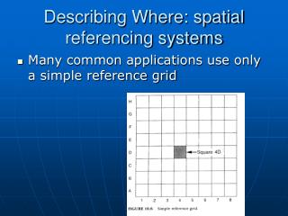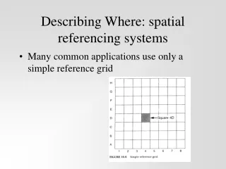
Spatial Referencing
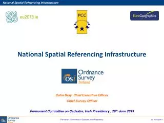
Spatial Referencing. Spatial Referencing. We know we are somewhere there! but how can we know where we are?. We are here!!!. Spatial Referencing. For that We need a reference. International Terrestrial Reference Frame(ITRF).

Spatial Referencing
E N D
Presentation Transcript
Spatial Referencing We know we are somewhere there! but how can we know where we are?
Spatial Referencing For that We need a reference
International Terrestrial Reference Frame(ITRF) The ITRS is realized through the International Terrestrial Reference Frame (ITRF), a catalogue of estimated coordinates (and velocities) at a particular epoch of several specific, identifiable points (or stations). These stations are more or less homogeneously distributed over the Earth surface. They can be thought of as defining the vertices of a fundamental polyhedron, a geometric abstraction of the Earth’s shape at the fundamental epoch
GIS user may encounter the following items in the map legend: • the name of the local vertical datum • the name of the local horizontal datum • the name of the reference ellipsoid and the fundamental point • the type of coordinates associated with the map grid lines • the map projection • the map scale • the transformation parameters from a global datum to the local horizontal datum.
Reference Model (reference ellipsoid) A reference system is then needed to be “put-on” a model that closely fits the surface of the earth. • In geometric geodesy, the earth is represented by an ellipsoid of revolution whose dimensions fits closely the surface of the earth. • This ellipsoid of revolution is known as the reference ellipsoid (other older literature termed this as “spheroid”). • The coordinate system and the reference system are the essential components of a reference framework.
Coordinate Systems • Three coordinate systems are commonly in use: • The Cartesian-Space Rectangular Coordinate System • The Geodetic Coordinate System • The Map-Grid Coordinate System
Cartesian-Space Rectangular Coordinate System a rectilinear type of coordinate system on a three-dimensional surface where the position of the points is expressed as coordinates of a righthanded orthogonal system whose origin coincides with the center of the ellipsoid, XZ-plane defines the zero meridian and XY plane defines the equator Uses (X,Y,Z) as its coordinate components
Geodetic Coordinate System (Geographic Coordinate System) a curvilinear type of coordinate system on three-dimensional space which uses a an surface to define the position of point on the earth. This coordinate system also uses three parameters to define the position of a point: 1. Geodetic latitude (φ): the angle between the ellipsoid normal through the point and the equator. (0≤ φ ≤ 90N or S) 2. Geodetic Longitude (λ): the angle in the equatorial plane between the zero meridian and the meridian of the point. (0 ≤ λ ≤180E or W) 3. Ellipsoidal height (h): the distance along the normal from the surface of the ellipsoid to point P.
Angle from equator: latitude Φ Angle east of Greenwich: longitude λ
Map-Grid Coordinate System (Projected Coordinate system) A rectilinear type of coordinate system on a planar surface where the horizontal position of a point is defined. The idea of which is to make the curved surface of the Earth by some mathematical transformation (map projection) into a plane. It uses basically two parameters to define the position of a point: Northing, N (or y) Easting, E (or x) • The third component of the position of a point which is the Elevation becomes an attribute in this coordinate system
Map Projections The creation of a map projection involves three steps: Selection of a model for the shape of the Earth or planetary body (usually choosing between a sphere or ellipsoid). Because the Earth's actual shape is irregular, information is lost in this step. Transformation of geographic coordinates (longitude and latitude) to plane coordinates (eastings and northings or x,y) Reduction of the scale (it does not matter in what order the second and third steps are performed)
Need for Projection!! Earth is ellipsoidal while maps are planner
Projection properties Distance, Area, and Shape Equal area projections:preserve the property of area. On an equivalent projection all parts of the earth's surface are shown with the correct area. However, latitudinal distances are never accurate. Conformal projections:preserve right angles between lines of latitude and longitude and are primarily used because they preserve direction. Area is always distorted on conformal maps. Equidistant:preserve correct distance relationships along a few lines on the map. For example, an equidistant azimuthal projection has the distance to the outside of the map portrayed correctly.
Local Projected Coordinates Palestine Grid
Local Projected Coordinates Israel Grid