Muscial Instrument Amplifier
360 likes | 569 Vues
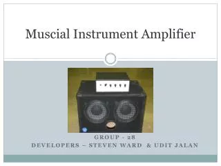
Muscial Instrument Amplifier. GROUP - 28 DEVELOPERS – STEVEN WARD & UDIT JALAN. Musical Instrument Amplifier. Introduction. Objective : Provide a low-cost, light weight alternative to current products in the industry

Muscial Instrument Amplifier
E N D
Presentation Transcript
Muscial Instrument Amplifier GROUP - 28 DEVELOPERS – STEVEN WARD & UDIT JALAN
Introduction • Objective: Provide a low-cost, light weight alternative to current products in the industry • Integrates three units: DSP Preamplifier, Class-D Amplifier and Switch-Mode Power Supply enhancing efficiency for less power consumption
Performance Features • 3-band digital equalizer with 16-way selection per band • 500 Watts R.M.S output power at 2 ohms • Frequency Response: 20Hz-20kHz +/- 3dB • Propagation delay less than 1ms • (THD + N) less than 0.5% at 50% rated output
Power Supply Unit • Switch-mode power supply delivering necessary voltages the amplifier and DSP units • Standard 120VAC input at less than 7A • All power supply outputs isolated from each other
Power Supply Design • Power ferrite transformer switched with 200V power MOSFETs in Half-Bridge configuration • Power MOSFETs feature low ON resistance of 35mOhms for efficient operation • Input surge current suppressed via 50 ohm resistor and bypassing, time-delay relay • Special electrolytic capacitors have low equivalent resistance for low power dissipation
Class-D Amplifier Unit • Amplifies analog input(1V RMS) to drive speaker(50V RMS) • Any standard ‘line level’ analog signal input • Independent of switching power supply unit, standard 60Hz transformer based power supply is used
Class-D Amplifier Design • High speed power MOSFETs with low ON resistance provide efficient operation • Precision Op Amps and high-speed comparator make up pre-stage of amplifier • Polypropylene film capacitor used on output filter for excellent high-frequency performance • Forced-air cooling for power devices • Clever self-oscillating design reduces part over “clocked” designs
DSP Preamplifier Unit • Performs filtering of analog signal in digital domain and outputs analog signal • Potentiometers used to set parameter values for filters • 4 knobs – volume, bass, treble, mid-band frequency • External 16-bit A/D and D/A converters used to ensure audio quality
DSP & Software • Microchip dsPIC30F4013 is a 16-bit processor • MPLAB C30 integrated development environment • Code written in C using “builtin functions” for DSP-specific math operations • Simple IIR filter algorithms require minimal computation cycles and memory use
Testing – Gain & Propagation Delay • Input of 200mV p-p using a function generator • Output measured across the speaker output of amplifier • Gain = (85.9V/0.2V) = 430V/V • Propagation Delay = 830us
(THD + N) Testing Limitations • Internal noise on the oscilloscope’s FFT = -71dB (with no probe connected) • Value changes to -50.6dB with probe connected. (probe is shorted out) • Due to this noise we have inherent limit on our (THD+N) measurements
Testing – (THD+N) of Source Generator • Input of 200mV p-p using a function generator • Frequency = 1kHz • FFT calculation of source generator alongside • THD+N = -47.2dB (third harmonic) • SNR = -57dB = 0.141% of input signal
Testing – (THD+N) – Full System • No Load • Input of 200mV p-p using a function generator • Frequency = 1kHz • FFT calculation of output at amplifier alongside • THD+N = -45.94dB
Testing – (THD+N) – Full System • Load of 5.8 Ohms (150W) • Input of 200mV p-p using a function generator • Frequency = 1kHz • FFT calculation of output at amplifier alongside • THD+N = -46.88dB
Testing – Power Supply • Ripple voltage on power supply generated for the amplifier is tested • Ripple voltage = 24mV is seen by probing the +/- 70 V line for the amplifier • Load of 40 Ohms (200W) produced 127V DC, voltage of +/-63.5V with 0.16Vrms of ripple at output • Load of 20 Ohms (333W) produced 114V DC, voltage of +/- 57V with 0.25Vrms of ripple at output
Testing – Amplifier • Feedback Phasing for proper self-oscillation • 130 ohm safety resistors on power supply • Static switching frequency: 300kHz • Output ripple (300kHz): 5.1v p-p • DC offset voltage at output of <1mVDC
Testing – Amplifier Power Output • Initial power tests used current limited bench power supplies • Next test used our switch-mode power supply with 130 ohm safety resistors to limit the current • Final testing removed the resistors for power testing up to 500W RMS into a 2 ohm resistive load • Speaker testing was performed up to 200W RMS • Amplifier efficiency was measured to be 81% with 213W output power
Testing – Amplifier Frequency Response • Second-Order output filter causes variation in high frequency response of the amplifier • Load alters the Q of the output filter • Output filter needs to be optimized for load for best high frequency response • Digital filters can compensate otherwise
Testing – Amplifier • Frequency modulation under load drops to 270kHz from 300kHz • Sample of amplifier switching with 20kHz audio input
Digital Filter Response - Bass Bass Boost Bass Cut
Digital Filter Response – Mid Band Mid-Band Boost Mid-Band Cut
Digital Filter Response - Treble Treble Boost Treble Cut
Challenges • dsPIC familiarity • C programming novice • DSP novice • Limited precision of DSP • Added noise • Filter stability • Power up issues • Surge Current • Speaker ‘pops’
Recommendations • DSP with greater bit-depth up to 32 bits for greater filter performance • Special audio effects: distortion, vibrato, reverb, delay, etc. • Output short-circuit protection • Smaller enclosure • Temperature sensor for fan speed control • Built-in practice speaker