Download
1 / 36
360 likes | 531 Vues
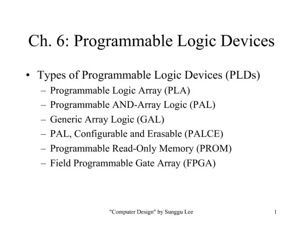
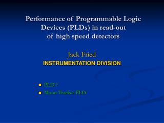
Performance of Programmable Logic Devices (PLDs) in read-out of high speed detectors. Jack Fried INSTRUMENTATION DIVISION. PLD ? Muon Tracker PLD. What Is a PLD. PLD Building Blocks. Logic Block. Device Features. PLD Features (cont). I/O Protocols. Design Entry. Plug In Manager.

E N D
Performance of Programmable Logic Devices (PLDs) in read-out of high speed detectors Jack Fried INSTRUMENTATION DIVISION • PLD ? • Muon Tracker PLD
Design Verification • Simulation • Built in real time Logic analyzer
Cathodes Read-Out Card (CROC) • Design Requirements • 64 Channel Readout per CROC • Less than 3125 electrons (RMS) noise for 10-150 pF of detector capacitance (including 24” cable) • • Less than 1% crosstalk between any channels on the board • gain: 3.5mV/fC • Digital/Analog isolation • Main Components • AMU-ADC • CPA digital Analog Signal
Controller Card (CNTL) • Design Requirements • Control AMU/ADC data collection, conversion and read-out • Provide connection to 2 CROC boards • Provide connection to the outside world • Support the T&FC and DCM interface • Provide data relay from remote controller board to DCM • Support ARCnet connectivity to serial configuration bus • FPGA - the brain • developed by Jack • work in progress CNTL Card
Requirements for Muon tracker PLD • Trigger rate 25Khz • 4 samples per pulse • Sample new data on every beam crossing • Holds 5 events • 100ns between triggers (burst rate) • Control digital part of AMUADC -RD-WR • Send data to DCM • Allow for Master and slave modes
Muon TrackerPLD Programming Difficulties • Board already designed • PLD already chosen (FLEX10K50E) • Pins allocated • PLD to small • Overlapping events • AMUADC noise problems • AMUADC requires special RD WR sequence
Memory Requirements • 4 samples per event • Need to be able to store 5 events • Each sample is 11bits • 32 channels per AMUADC • 4 AMUADC PER CNTL 128 channels 28160 BITS TOTAL
Memory Implementation • Used 9 EABs • Only 1 EAB left for PLD algorithm • Lost 8704 bits
Muon FEE • PLD - current code • store every beam crossing • 4-sample per pulse • readout time 53uS • hold 4 events Time