Download
1 / 40
700 likes | 1.63k Vues
Chapter 4 Crystal Defects and Noncrystalline Structure–Imperfection.

E N D
Chapter4Crystal Defects and Noncrystalline Structure–Imperfection
In Ch. 3, wide variety of atomic-scale structures in the engineering materials were shown. The structures were perfect structures without any defects. However, in practice, there may be several different kind of defects with different amount for the different conditions. A visual example for the possible defects in metals, crystalline structure; (This model is visualized with soap bubbles, but it explains the defects well.)
Defects in crystalline solids : 1). Point Defect ①. Impurity : In an alloy some unwanted elements may be existed. ②. Vacancy : Missing atom from the lattice point. (There may be several different types of vacancies, they will be explained more in the later chapters.) 2). Line Defect Dislocation : Edge, screw and mixed dislocations 3). Planar Defect ①. Grain boundary ②. Twin boundary ③. Anti-phase domain boundary 4). Volumetric Defect Void, Cracks, Shrinkage, inclusion, etc.
4.1 The Solid Solution-Chemical Imperfection The complete solubility of alcohol in water is the result of complete molecular mixing. Figure 4.1Forming a liquid solution of water and alcohol. Mixing occurs on the molecular scale. Liquid solution Then, what is solid solution?
Complete solid solubility Cu and Ni have complete solid solubility system. Figure 4.2Solid solution of nickel in copper shown along a (100) plane. This is a substitutional solid solution with nickel atoms substituting for copper atoms on fcc atom sites. (Random solid solution) Cu : solvent, Ni : solute, Substitutional solid solution Hume-Rothery rules : explain the complete miscibility to occur in metals. 1). Less than about 15% difference in atomic radii 2). The same crystal structure 3). Similar electronegativies (the ability of the atom to attract an electron) 4). The same valence
Figure 4.3Ordering of the solid solution in the AuCu3alloy system. (a) Above ~390°C, there is a random distribution of the Au and Cu atoms among the fcc sites. (b) Below ~390°C, the Au atoms preferentially occupy the corner positions in the unit cell, giving a simple cubic Bravais lattice. (AuCu3 structure) Below 390oC, Cu atoms preferentially occupy the face-centered positions, and Au atoms preferentially occupy corner positions. Ordering may produce a new crystal structure similar to some of the ceramic compound structures, AuCu3. Above 390oC, thermal agitation makes the alloy disordered or random distribution of solutes.
Figure 4.4Interstitial solid solution of carbon in α-iron. The carbon atom is small enough to fit with some strain in the interstice (or opening) among adjacent Fe atoms in this structure of importance to the steel industry. [This unit-cell structure can be compared with that shown in Figure 3.4b.] (Octahedral void) Carbon is too small to be dissolved substitutionally. Asit has been explained in Ch. 3, since the octahedral void in BCC is the smallest interstitial site (r = 0.154 R), if the carbon is located in this site, it produces very considerable strain locally to the α-Fe crystal structure, and less than 0.1at.% carbon is soluble in α-Fe. The reason why carbon atom locates in the smallest void in α-Fe is explained in Ch. 10.
In ionic compounds, the oxygen ion usually affects dissolution of the solute in ceramics. But not in this NiO – MgO system. Therefore, Ni2+ and Mg2+ , which have same valences, are randomly or substitutionally mixed. Figure 4.5Random, substitutional solid solution of NiO in MgO. The O2−arrangement is unaffected. The substitution occurs among Ni2+and Mg2+ions. Same valences.
Because of the different valences and structures between Al2O3 and MgO, the mixing is not as simple as NiO-MgO system. Therefore, for the charge neutrality O2- has some role, and in the overall compound permits only two Al3+ ions to fill every threeMg2+ vacant sites, leaving one Mg2+ vacancy. Figure 4.6A substitutional solid solution of Al2O3in MgO is not as simple as the case of NiO in MgO (Figure 4.5). The requirement of charge neutrality in the overall compound permits only two Al3+ions to fill every threeMg2+vacant sites, leaving oneMg2+vacancy.
For the case of nonstoichiometric compound of Fe1-xO, some more Fe ion is necessary to form FeO compound with equal number of Fe2+ and O2-. However, ideal FeO is never found in nature due to the multivalent nature of Iron, Fe2+ and Fe3+ . Therefore, both Fe2+and Fe3+ions occupy the cation sites, with one Fe2+vacancy occurring for every two Fe3+ions present. Figure 4.7Iron oxide, Fe1−xO with x ≈ 0.05, is an example of a nonstoichiometric compound. Similar to the case of Figure 4.6, both Fe2+and Fe3+ions occupy the cation sites, with one Fe2+vacancy occurring for every two Fe3+ions present.
Examples and Practice Problems : Students are asked to review the “Example” of 4.1, and4.2 and solve the “Practice Problem” of 4.1, and4.2 in the text.
4.2 Point Defects Zero-Dimensional Imperfections Inthe previous section, we have considered Chemical Imperfections. Here in the following sections, Structural Defects are discussed. At the beginning of this chapter, brief introduction for the various defects was discussed. In this section, Point Defects (zero-dimensional imperfections) will be discussed. These defects are mainly resulting from the thermal agitation of the lattices. 1). Vacancy : Unoccupied atom site in the crystal structure by missing atom. 2). Interstitial or interstitialcy : Occupying an interstitial site not normally occupied by an atom in the perfect crystal or an extra atom inserted into the perfect crystal structure such that two atoms occupy positions close to a singly occupied atomic site in the perfect structure. These two defects are shown in Fig. 4.8, next slide.
in Figure 4.8Two common point defects in metal or elemental semiconductor structures are the vacancy and the interstitial. out compressive stress condition tensile stress condition
x Figure 4.9Two common point defect structures in compound structures are the Schottky defect and the Frenkel defect. Note their similarity to the structures shown in Figure 4.8. move x Frankel Defect : out Vacancy-interstitialcy combines not to loose charge neutrality. The small ion (cation) moves to the interstitial site to form their compound. Usually, if two cations comes together, the local stress becomes very high. Therefore, it is not common, however, CaF2-type can accommodates without excessive lattice strain. Ex : AgBr2. Schotty Defect : To maintain the charge neutrality, a pair of oppositely charged ions are out of structure.
Examples and Practice Problems : Students are asked to review the “Example” of 4.3 and solve the “Practice Problem” of 4.3 in the text.
4.3 Linear defects or Dislocations One-Dimensional Imperfections While point defects are known to be generated by thermal agitation, linear defects are associated primarily with mechanical deformation. Dislocation : line defect, several terminologies and symbol, ; 1). Edge dislocation. 2). Screw dislocation. 3). Mixed dislocation. 4). Burger’s vector, b, and line sense, ξ 5). Slip plane, extra half plane. 6). Slip direction. 7). Dislocation loop. 8). Cross slip. See Fig. 4.10 ~ Fig. 4.14 for the detailed explanations.
τ (applied shear stress) Figure 4.10Edge dislocation. The linear defect is represented by the edge of an extra half-plane of atoms. Extra half plane Slip direction : direction to which dislocation moves by shear stress. Slip plane : dislocation moving plane. Dislocation line : line of atoms without pair. (Line sense, ξ: the direction looking into the edge dislocation line.) Lattice constant = Magnitude of Burger’s vector
5 S In the perfect crystal, an 5× 4 atomic step loop closes at the starting-finishing point. No problem! F 4 Figure 4.11Definition of the Burgers vector, b, relative to an edge dislocation. (a) In the perfect crystal, an m× n atomic step loop closes at the starting point. (b) In the region of a dislocation, the same loop does not close, and the closure vector (b) represents the magnitude of the structural defect. For the edge dislocation, the Burgers vector is perpendicular to the dislocation line. 4 5 In the region of an edge dislocation, the same loop does not close, and the closure failure represents the Burger’s vector and the magnitude of the Burger’s vector (b) is same as the closure failure, which is the lattice constant, α. S F Burger’s vector is perpendicular to the edge dislocation line and same as the moving direction. Closure failure
ξ Unsliped plane Screw dislocation is little bit difficult to show compared to the edge dislocation, however, the concept is exactly same. Slip direction Slipped plane Figure 4.12Screw dislocation. The spiral stacking of crystal planes leads to the Burgers vector being parallel to the dislocation line. S Burger’s vector is parallel to the screw dislocation line and perpendicular to the slip direction. τ F There is no extra-half plane in the screw dislocation. Slip plane τ
All the Burger’s vectors are in the same direction regardless position. Mixed Figure 4.13Mixed dislocation. This dislocation has both edge and screw character with a single Burgers vector consistent with the pure edge and pure screw regions. Slip plane ξ Unslipped region ξ Screw ξ Edge Slipped region Once the line sense is decided it has to be following the dislocation line, and for curved region the line sense is the tangent direction of the line.
Different from metals, the ceramic is composed with different ion with different sizes. Therefore, the structure is very complicated and the ion pairs have to move together, it is not easy for the dislocation in ceramics to move. This makes the ceramic brittle. Figure 4.14Burgers vector for the aluminum oxide structure. The large repeat distance in this relatively complex structure causes the Burgers vector to be broken up into two (for O2−) or four (for Al3+) partial dislocations, each representing a smaller slip step. This complexity is associated with the brittleness of ceramics compared with metals.
Examples and Practice Problems : Students are asked to review the “Example” of 4.4 and solve the “Practice Problem” of 4.4 in the text.
4.4 Planar Defects Two-Dimensional Imperfections Planar defects are larger sized defects compared with point and line defects. Planar defect is a kind of surface, and this surface is a disruption of the atomic-stacking arrangement of crystal. There are various forms of Planar defects, and they are; 1). Twin boundary (Fig. 4.15) : Separates two crystalline regions that are mirror images of each other. 2). Free surface (Fig. 4.16) : A simple schematic view of the crystalline surface. This illustration shows that the surface atoms are some how different states. 3). Edgelike surface (Fig. 4.17) : Hirth-Pound model of a crystal surface that has elaborate ledge systems rather than atomically smooth planes. 4). Grain boundary (Fig. 4.18) : The most important planar defect for our lecture is this boundary and it is known as the region between adjacent single crystals or grains. 5). Anti-phase domain boundary : Not introduced in this text book. (For ceramics)
Figure 4.15A twin boundary separates two crystalline regions that are, structurally, mirror images of each other. Twining is a special way of deformation. Those crystal structures whose slip system is limited, i. e., HCP and some BCC, may deform by twining and leave twin boundare after deformation. (habit plane, twin direction, twin distance, ect.)
Looking carefully, one may realize the atoms at surface have different shape. This symbolized that the surface atoms are not stable but chemically unstable. Gradual shape change of atoms from inside toward surface means that chemical instability is increasing toward surface. Surface tends to be reacted fast, i.e., easy oxidation. ellipsoid Complete circle Free Surface Figure 4.16Simple schematic view of the surface of a crystalline material.
This model emphasize that the atomic structure of surface is not smooth, but it has the crystal surface having atomic scale elaborate ledge systems. Hirth-Pound Model Figure 4.17A more detailed model of the elaborate ledgelike structure of the surface of a crystalline material. Each cube represents a single atom.
Every grain meets other grains with different crystallographic orientations to make the grain boundaries. In other words, GB line is the border line between two different single crystals with different orientations. Most engineering materials are polycrystalline, except electronic materials. The more grain boundaries, the smaller the grain size. Grain size is one of the very important factors which influences the mechanical properties (i.e., strength and ductility), Figure 4.18Typical optical micrograph of a grain structure, 100×. The material is a low-carbon steel. The grain boundaries have been lightly etched with a chemical solution so that they reflect light differently from the polished grains, thereby giving a distinctive contrast. The atomic scale grain boundary structure greatly depends on the relative orientations of the adjacent grains, high and/or low angle GB.
Tilt angle Tilt ledge A typical model of low angle GB. However, the high angle GB can also be explained with this model. Grain boundary dislocation Figure 4.19Simple grain-boundary structure. This is termed a tilt boundary because it is formed when two adjacent crystalline grains are tilted relative to each other by a few degrees (θ). The resulting structure is equivalent to isolated edge dislocations separated by the distance b/θ, where b is the length of the Burgers vector, b. This model is theoretically based and also experimentally proved to be reasonable. This model suggests that the tilt ledge is considered to be the grain boundary dislocation
In describing the microstructure and comparing the mechanical properties of metallic materials, it is useful to have a simple index of grain size. Figure 4.20Specimen for the calculation of the grain-size number, G, 100×. The material is a low-carbon steel similar to that shown in Figure 4.18. ASTM standard for Grain-size number, (G) N = 2G-1 Where N is the number of grain observed un an area of 1 in2 on a photo taken with x100 mag. As N increases, G also increases.
22 (Since the 22 grains contains also in the adjacent grain, should be divided by 2.)
Another Index for grain size : grain diameter, d, As it has been indicated in the previous sample calculation, thegrain-size number, G, is known to be not so perfect index. Therefore, it would be useful to obtain an average value of grain diameter from a microstructural section. (this is not also a perfect approach but good!) A simple indicator is to count the number of grains intersected per unit length, nL, of a random line drawn across a micrograph. The average grain size is roughly by the inverse of nL, corrected for the magnification, M, of the micrograph. Of course, one must consider that the random line cutting across the micrograph (in itself, a random plane cutting through the microstructure) will not tend, on average, to go along the maximum diameter of a given grain. C In general, then, the true average grain diameter, d, is given by d = nL M where, C is a constant of 1.5 for typical microstructures.
Examples and Practice Problems : Students are asked to review the “Example” of 4.5 and 4.6 and solve the “Practice Problem” of 4.5 and 4.6 in the text.
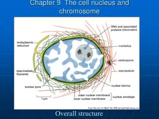
4.5 Noncrystalline Solids Three-Dimensional Imperfections There are some engineering materials whose structures are not crystalline. These non-crystalline or amorphous solids are imperfect in three dimensions. Figure 4.21Two-dimensional schematics give a comparison of (a) a crystalline oxide and (b) a noncrystalline oxide. The noncrystalline material retains short-range order (the triangularly coordinated building block), but loses long-range order (crystallinity). This illustration was also used to define glass in Chapter 1 (Figure 1.8). Oxide glass sreucture a b Si4+ O2- crystalline oxide Zachariasen model of noncrystalline oxide 3- Long-range order or crystallinity is maintained with the building block of the crystal, SiO3, “triangle”. Short-range order with SiO3, “triangle” is still main-tained even though it loses long-range order. 3-
4.5 Noncrystalline Solids--Three-Dimensional Imperfections (Continued) Explanation of the Fig. 4.21 : In this figure, ionic arrangement of the glass is shown for (a) crystal structure, And (b) non-crystal stricture. Figure (a) : It shows the long-range order of the building block of the crystal,SiO3, (triangle in two dimensional view). The typical crystal structural shape of the ionic crystal, i.e., anion and cation makes a building block. The real building block of the glass crystal in 3 dimension is SiO4, tetrahedra. 3- 4- Figure (b) : It shows the non-crystal structure of glass. Therefore, the long-range order of the build block is not maintained, however, the building block is still remaining. This figure is a schematic drawing by the “Zachariasen Model” for the visual definition of the random network theory.
Figure 4.22Bernal model of an amorphous metal structure. The irregular stacking of atoms is represented as a connected set of polyhedra. Each polyhedron is produced by drawing lines between the centers of adjacent atoms. Such polyhedra are irregular in shape and the stacking is not repetitive.
The role of the modifier is to be discussed later, for ceramics. Figure 4.23A chemical impurity such as Na+is a glass modifier, breaking up the random network and leaving nonbridging oxygen ions.
This figure shows some part for crystal and some other part for non-crystal. → medium-range ordering Figure 4.24Schematic illustration of medium-range ordering in a CaO–SiO2glass. Edge-sharing CaO6octahedra have been identified by neutron-diffraction experiments.
Examples and Practice Problems : Students are asked to review the “Example” of 4.7 and solve the “Practice Problem” of 4.7 in the text. The end of Ch. 4.