MaPMT Electronics Schemes.
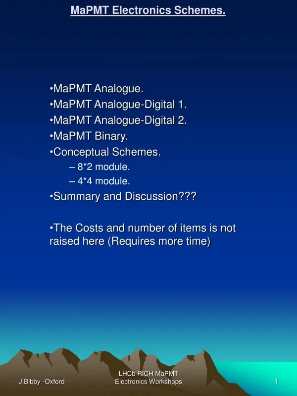
MaPMT Electronics Schemes. MaPMT Analogue. MaPMT Analogue-Digital 1. MaPMT Analogue-Digital 2. MaPMT Binary. Conceptual Schemes. 8*2 module. 4*4 module. Summary and Discussion??? The Costs and number of items is not raised here (Requires more time). MaPMT Analogue.

MaPMT Electronics Schemes.
E N D
Presentation Transcript
MaPMT Electronics Schemes. MaPMT Analogue. MaPMT Analogue-Digital 1. MaPMT Analogue-Digital 2. MaPMT Binary. Conceptual Schemes. 8*2 module. 4*4 module. Summary and Discussion??? The Costs and number of items is not raised here (Requires more time) LHCb RICH MaPMT Electronics Workshops
MaPMT Analogue. 16 MaPMTs +DividerChain+BEETLE. 2*8 or 4*4 Module MaPMT Module RAD HARD TTC,ECS, Power Supplies FPGA-MINT. 1 TTCrx; 1 MINT; ECS; Drivers/receivers. Level-0 Interface. Links—twisted pair copper. 32 pairs per module. Rad Hard Line drivers Cu Data Links Distance and location of L-1 Electronics from L-0. ( COTS To Be or Not To Be??) 60Metres!!!! Distance Common L-1 Module or our own. If we use our own then current expertise is not wasted. Front-end will need to be re-designed. Note that if L-1 is Located in the Cavern area then Level-1 may have to be Rad tolerant. COTs Receivers, FPGAs, Memory. Level-1 DAQ. LHCb RICH MaPMT Electronics Workshops
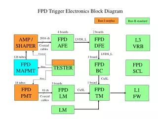
Analogue Block Diag. MaPMT-1 MaPMT-2 CLK./Trig BEETLE/Output Buffers MINT Power Supply Filtering. HT and LV. TTC/ECS. 4Off Twisted pair/BEETLE(32 off per L-0 module). Packing and Synchronising the data into the L-1 Buffers. TTC without the QPLL will be required. Number of Channels/L-1 module??? FADC FADC FADC FADC 8 bits 8 bits 8 bits 8 bits LHCb RICH MaPMT Electronics Workshops
MaPMT Analogue. Notes: • Power dissipation/L-0 module ~ (10+)Watts • Power dissipation /L-0 interface = • Copper links. (1) Costs = • Total number of links = • Total link costs. (2) = • Distance for links is Limited. <60Metres. • S/N degrade over such a long distance in copper. • Implications on the Level-1 electronics. • Many copper cables around detector plane. • Restriction on cooling and access. • Fragile and bulky connectors!!. • BUT. • Raw data available—But note S/N above. • TTCrx only required (No QPLL). • MINT expertise available. LHCb RICH MaPMT Electronics Workshops
MaPMT Analogue-Digital-1. 16 MaPMTs+BEETLE +Divider Chain. 2*8 or 4*4 Module MaPMT Module RAD HARD TTC,ECS, Power Supplies, FPGA-MINT. 1 TTCrx; MINT1; ECS; Drivers/receivers. Level-0 Interface. Links—twisted pair copper. 32 pairs per module. Rad Hard Line drivers Cu Data Links Distance and location of Fibre driver Electronics from L-0. <40Metres!!!! Distance FADC-GOLS-MINT2-Trigger QPLL/TTCrx!! 8 fibre links/module. Fibre Data Links <60Metres!!!! Common L-1 Module or our own. If we use our own then current expertise is not wasted. Front-end will need to be re-designed.. COTs Receivers, FPGAs, Memory. Level-1 DAQ. LHCb RICH MaPMT Electronics Workshops
Analogue-Digital-1 Block Diag MaPMT-1 MaPMT-2 CLK./Trig BEETLE/Output Buffers MINT1 Power Supply Filtering. HT and LV. TTC/ECS. 4Off Twisted pair/BEETLE(32 off per L-0 module). TTC/QPLL FADC Power Supply Filtering.. FADC FADC FADC 8 bits 8 bits 8 bits 8 bits GOL MINT2 8*1Off/module Level-1 located at Control Room. Number of Channels/L-1 module??? LHCb RICH MaPMT Electronics Workshops
Analogue-Digital-1. Notes: • Similar to MaPMT analogue except: • Two Interface/module regions before L-1. • Simple Rad hard MINT1. • Level-1 can be located in the counting room • L-0 more expensive—L-1 less -- • Will require (Rad Tolerant!!)MINT2. • TTCrx plus TTCrx/QPLL. • More interconnections—(Recipe for disaster) • Additional power supply infrastructure. • In its favour—L-1 is counting room based. LHCb RICH MaPMT Electronics Workshops
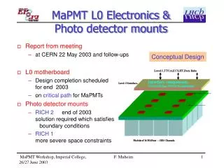
MaPMT Analogue-Digital-2. 16 MaPMTs +BEETLE Divider Chain. 2*8 or 4*4 Module MaPMT Module RAD HARD TTC,ECS, FADC, GOLS, VCSELs. Power Supplies FPGA-MINT. 1 TTCrx; 1 MINT; ECS; Drivers/receivers. Level-0 Interface. Links—Fibre 8 per module. FIBRE Data Links Distance and location of L-1 Electronics from L-0. ( COTS To Be). 100Metres Distance Common L-1 Module or our own. If we use our own then current expertise is not wasted. Front-end will need to be re-designed. COTs De-Serialisers, FPGAs, Memory. Level-1 DAQ. LHCb RICH MaPMT Electronics Workshops
MaPMT-1 MaPMT-2 BEETLE/Output Buffers Analogue-Digital-2 Block Diag. FADC FADC FADC FADC Power Supply Filtering. HT and LV. 8 bits 8 bits 8 bits 8 bits MINT 32 bits GOL/VCSEL CLK. DW/CW TTC/QPLL ECS. Serialised Data to L-1 De-serialise/checking and packing the data into the L-1 Buffers. TTC/QPLL will be required. Number of Channels/module??? LHCb RICH MaPMT Electronics Workshops
Analogue-Digital-2. Notes : • Scheme shows block for one BEETLEs worth. • The scheme also assumes that the dynamic range for the FADC is 8 bits. Channel, Pipeline address and baseline offsets need to be considered. • The GOLs have to function in 32:1 mode. • TTC/QPLL will be necessary. • One module to contain 16 MaPMTs, 8 BEETLEs, 8fibres—decision?? • Major cost items will be the support board (BLEEDER/BEETLE) and the fibres. • Power per module-- >12Watts!!! To be properly calculated. • Constraints on design/layout due to necessary cooling scheme(s). • Feasible?—Design studies required on the BLEEDER/BEETLE/L-0 interface board. Can they mechanically fit into RICH 1 and 2. Other major electronics items have been evaluated by various LHCb groups (IT-MUON). • Available FPGA expertise for the MINT. Rad hard ACTEL type device needs to be resolved--- . • Power supply and distribution schemes need to be designed and evaluated----- • Data fibres to be defined—we should collaborate with IT and Muons on this. • Basic architecture is similar to IT—we could collaborate on RAD Hard qualification. • Level-1 design is an evolvement of the current Binary design. “X” fibre channels per module. • De-serialiser could be the Texas TLK2501IRCP LHCb RICH MaPMT Electronics Workshops
MaPMT Binary. 16 or 32 MaPMT+BEETLE +Divider Chain. 2*8 or 4*4 or 2*16 Module MaPMT Module RAD HARD TTC,ECS, GOLS,VCSELs. Power Supplies FPGA-MINT. 1 TTCrx; 1 MINT; ECS; Drivers/receivers. Level-0 Links—Fibre 1 per module. GOL/VCSEL One per module. Data Links Distance and location of L-1 Electronics from L-0. 100Metres Distance Common L-1 Module or our own. If we use our own then current expertise is not wasted. Front-end will need to be re-designed. COTs De-Serialiser, FPGAs, Memory. Level-1 DAQ. LHCb RICH MaPMT Electronics Workshops
Binary Block Diag. MaPMT-1 MaPMT-2 BEETLE/Output Buffers 32 links/module Power Supply Filtering. HT and LV. MINT 32 bits GOL/VCSEL CLK. DW/CW TTC/QPLL ECS. 1 Fibre/module Serialised Data to L-1 De-serialise/checking and packing the data into the L-1 Buffers. TTCrx will be required. Number of Channels/module??? Use currently developed module. LHCb RICH MaPMT Electronics Workshops
Binary Notes: • BEETLE has to be shown to work in this mode. • What is the spread in gain over all MaPMTs and within an MaPMT. • The BEETLE Fine discriminator threshold range, for each channel, will have to match these—this issue may take some time to be settled!!!! • Is the expected photon efficiency acceptable when using MaPMTs in the Binary mode. • Current expertise within the RICH group on Fibres, L-0 and L-1 can be built-on to get such a system quickly up and running. LHCb RICH MaPMT Electronics Workshops
Modularity.8*2 Module. (Conceptual) MaPMTs. BLEEDER/BEETLE.. BEETLEs BUFFER/DRIVERs. LEVEL-0 Interface. LHCb RICH MaPMT Electronics Workshops
Modularity.4*4 Module (Conceptual) BEETLEs BUFFER DRIVERs. MaPMTs. LEVEL-0 Interface. BLEEDER/BEETLE.. LHCb RICH MaPMT Electronics Workshops
Summarise (Discussion) • Schemes. • Outline Major differences. • Location of L-1. • Link lengths. • Power supplies. • Cooling. • Maintenance/accessibility • Links. • Fibre Link costs(3) (each)=252CH • Copper Link costs (4) • Total number • FED range. • Assume 8 bits.????(See next slide) • Modularity • MaPMT. (16 off) • 8*2 or 4*4. BLEEDER/BEETLE • L-0 Interface • Links. • L-1 • On-Detector Cooling. • ~10 watts perBLEEDER/BEETLE module. • ~ 2 watts per Level-0 Interface • Preference—Flag • Analogue Digital-2. • COSTS--------------------------- • More work effort required for this. LHCb RICH MaPMT Electronics Workshops
BEETLE 1.2 Baseline. LHCb RICH MaPMT Electronics Workshops