Download
1 / 22
220 likes | 401 Vues
MICE RF Daresbury Laboratory Support Joe Orrett - ASTeC. Personnel. Daresbury Laboratory RF and Diagnostics Group will provide three members to support the MICE Project; Andrew Moss – Senior RF engineer Joe Orrett – RF engineer Peter Corlett – RF engineer. RF System.

E N D
Personnel Daresbury Laboratory RF and Diagnostics Group will provide three members to support the MICE Project; • Andrew Moss – Senior RF engineer • Joe Orrett – RF engineer • Peter Corlett – RF engineer 2
RF System • Discussions between the DL staff, Paul Drumm and Roy Church on the 6,7th October agreed the initial thoughts on development of the MICE RF test stand • The brief is to rebuild one 2MW amplifier to test the feasibility of the system to power the MICE RF system 3
Master Oscillator Controls etc Los Alamos CERN HT Supplies 300 kW Amplifier 300 kW Amplifier 300 kW Amplifier 300 kW Amplifier 2 MW Amplifier 2 MW Amplifier 2 MW Amplifier 2 MW Amplifier HT Supplies LBNL Daresbury 201 MHz Cavity Module 201 MHz Cavity Module 4
DL Support Areas • Modelling • Extensive simulation tools • Refurbishment • equipment from LBNL, CERN • Design • Low level control electronics • Recommissioning • Loaned equipment into a test stand 7
Modelling • DL RF and Diagnostic Group has the capability to model RF systems using Microwave Studio and HFSS • Aspects of the proposed RF system can be simulated and potential problems identified • A 2MW test load made from 4 50KW loads is a prime candidate for this process • Hybrid power splitters/circulators will also be modelled 8
Modelling example • 1.3GHz power combining/splitting cavity modelled • Low power test cavity manufactured at DL • Simulation and testing agreed 99% 9 Courtesy of Emma Wooldridge, ASTeC
Refurbishment We will be receiving equipment from various labs which, in most cases has not been in service for a considerable length of time. Upon arrival the following actions will be carried out; • Inspection, each item will dismantled and inspected for mechanical and electrical integrity. Any remedial action required will be identified. 10
Mechanical/electrical refurbishment • Refurbishment, mechanical items will be refurbished to an acceptable standard using the DL Workshop Facilities. • Modification, it is likely that much of the electrical equipment will require some modification:- • Heater power supplies and controls • Cathode modulation system • HT supplies 11
Testing • Testing, if practical, discrete components will be independently tested before being assembled into the RF System. • Coax sections • Matching devices • HT supplies • Low level electronic components 12
Design of Low Level RF electronics • DL mainly works at 500MHz CW • Many Interesting RF devices could be tested as part of the MICE program • Hope to build and collaborate with RAL experience • Copy existing designs for time critical components • Use test stand to develop new ideas and solutions 13
Recommissioning • Recommissioning is likely to be a challenging process! • Old, out of service equipments being reassembled in a new system are bound to cause problems. 14
4616 Circuit • LBNL sending 4616 test stand • Need to find one more driver for MICE 15
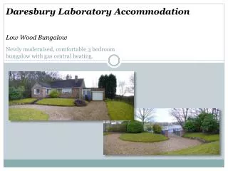
Electrical plant room location • 415V plant room • Large cooling supplies under floor area • The area to be cleared • Make use of Bund area? • Overhead crane • Large access doors 16
MICE equipment • LBNL circuits should be arriving very soon • CERN modulator for 2MW circuit, discussions continue • 4616 LANL PSU, MOU under construction 17
2.5MW HT • A modulator from the CERN test stand has become available; this will provide 150A at 32KV at 1Hz 200uS. Discussions are in progress to see if this can be brought to DL • I think the conclusion is that this will be useful to the MICE RF & DL will … 18
Heater • The heater runs at 17V 450 amps, the psu should come with the equipment, but might need to be refurbished. RAL have a new design for this. Running the heater to high will result in a considerable reduction in lifetime for the tube. Back heating of the tube heater may occur from the RF drive! 19
Ion pumps • The circuits use 5KV varian Ion pumps, which are used on site at DL • Safety issues • At RAL no X Ray problems have been found in running the tubes, • Tests at DL will need to be carried out by Heath Physics as soon as HT is applied to the tubes. 20
Test Load • a coaxial 4-way splitter and four 50KW loads: model various arrangements and purchase commercially available equipment. • TH170 • If the TH116 proves an unsuccessful candidate, CERN use TH 170 tubes for a similar power level, however the input impedance of these tubes is dramatically different and the 170 needs a tuning stub, CERN will be able to help with this. • Anode dissipation of the tubes is 50KW and 10KW for the 116 & 170 respectively. • Conditioning of these tubes could take up to a day. Reduced HT and low drive levels are needed to slowly bring tube up to full power. Resonance effects can be cured by using ferrite absorbers in the output cavity and resistor/capacitor networks on the drive connections. • 4616 Drivers • Manufactured by Burle industries a test stand for the 4616 will be included in the shipment from Berkley as well as 3 circuits (a forth will be needed), Burle are supposed to be finding drawings of the circuits used at Berkley. • The tubes should come with all the systems ready to drive them, heater, grid and HT psu’s, and input/output matching sections, but extensive refurbishment will be needed. • HT • The 18KV psu for the HT is currently at LANL, PD is liaising with John Lyles over an MOU. The tube is operated with DC HT and pulsing the screen grid, JL has a design using mosfets to do this. Screen grid psu information is available from Burle. 21
As yet there is no news of the shipment • Hope to know before end of week • and hopefully, tomorrow! 22