Download
1 / 38
380 likes | 572 Vues
AEI 10m Prototype. AEI 10 m Prototype and its Suspension Platform Interferometer. Katrin Dahl for the AEI 10 m Prototype team. The team. Ken Strain: Scientific Leader of the 10m Prototype StefanGoßler : Coordinator, Leader QUEST Research Group

E N D
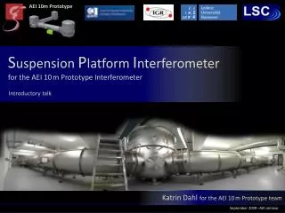
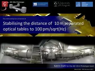
AEI 10m Prototype AEI 10 m Prototype and its Suspension Platform Interferometer Katrin Dahl for the AEI 10 m Prototype team
The team • Ken Strain: Scientific Leader of the 10m Prototype • StefanGoßler: Coordinator, Leader QUEST Research Group • BennoWillke : Leader QUEST task group, high power laser • HaraldLück: Pretty much everything... • KasemMossavi: Vacuum system, infrastructure • Stefan Hild : Interferometer sensing and control • KentaroSomyia: Theory @ Caltech • Alessandro Bertolini: Isolation Tables • Michael Born: CDS, Interface SPI2CDS • Fumiko Kawazoe:Frequency-Reference Cavity design and control • GerritKühn : CDS and related infrastructure • Bob Taylor: Suspension Systems • Katrin Dahl : Suspension Platform Interferometer • Christian Gräf : Digital Control • Tobias Westphal : Monolithic suspensions, IFO-control • Alexander Wanner : Seismic Isolation • Oliver Kranz : Suspension Platform Interferometer • Daniel Gering : Interface SPI2CDS • Andreas Weidner: Electronics Senior staff scientist Staff scientist Lecturer Research Fellow Postdoctoral Research Fellow Ph.D Students Diploma Student
AEI 10m Prototype and its Suspension Platform Interferometer AEI 10m Prototype
The AEI 10m Prototype Goals: • Maximal overlap with GEO-HF subsystems • develop and prove as many of the techniques needed for GEO 600 upgrades as possible (e.g. PSL, digital control infrastructure) • provide training for people who will install and run GEO-HF • Provideultralowdisplacementnoisetestingenvironment • To probe at (and later go beyond) the SQL • Entanglement of macroscopic test masses • For geodesy/LISA related experiments • ...
IFO • 100g mirrors • triple cascaded pendulum • suspensions • Frequency reference cavity: • Finesse ~7500 • roundtrip length 24.6m • mirrors 850g • Triple cascade all steel wire • pendulum suspension • monolithic all-silica last stage • silica suspension filaments of • 28µm diameter
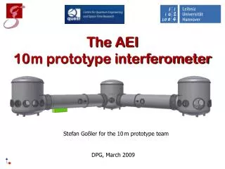
Vacuum system Tank centers separatedby11.65m Volume ca. 100 m3 22 t stainless steel Tubes: 1.5 m diameter Tanks: 3 m diameter, 3.4 m tall • Roughing: One 170 l/s screw pump • Main pumps: Two 2000 l/s turbo-molecularpumps • Backingand differential pumping: Two scroll pumps
270° view • After 12 hours of pumping 10-6mbar • After about one week of pumping 10-7mbar
Walk-in tanks 100mm flanges to fit feedthroughs Doorintothe tank 600mm flanges to fit viewports 100mm flanges to fit feedthroughs
Seismic Attenuation System One SAS per vacuum tank, optical table goes on top of SAS Improved version of HAM-SAS Resonance frequency around 0.1Hz Up to 80dB attenuation in both vertical and horizontal directions Angstrom residual motion above 1Hz Relative residual motions between the tables will be detected and stabilised by the SPI
AEI 10m Prototype and its Suspension Platform Interferometer SPI
Why a Suspension Platform Interferometer? • Ease lock acquisition of cavities by reducing residual test mass motion • Reduction of burden to actuators on the mirrors • Testbed for GRACE follow-on and LISA related experiments Sets requirements on SPI
THE SPI • Requirements: • No specific lock point • Control bandwidth 100 Hz • 100pm/sqrt(Hz) and 10nrad/sqrt(Hz) @ 10mHz • Heterodyne Mach-Zehnderinterferometry • Suits our needs best • In-house knowledge
Measurement bench • Beam height 45mm • Overall height below 65mm
Phase determination Phase isextractedfromheterodynesignalbyuse of an hardware Phasemeter1based on FPGA chips • Preamplifierand A/D conversion • Photocurrentconvertedtovoltage • Digitisingsignals • results in time series • Single bin discrete Fourier transform • Fourier transformatonlyonefrequency • complexamplitudeof PD signalatfhet • Signal combinationofeach QPD quadrantleadstophase, DC, Differential WavefrontSensing (DWS) andcontrastinformation Illustration of DWS 1 developed for LISA Pathfinder, Heinzel G et al. 2004 Class Quantum Grav21 581
Choice of parameters • Due to the arm length mismatch (20m optical path length) a highly stabilised laser is necessary: • 140Hz/sqrt(Hz) @ 10mHz for IR light (1064nm)
Iodine stabilised Nd:YAG laser output power: 1W Stabilisation via Modulation Transfer Spectroscopy Michael Tröbs
Choice of parameters • According to the arm length mismatch (20m optical path length) a highly stabilised laser is necessary: • 140Hz/sqrt(Hz) @ 10mHz for IR light (1064nm) • Control bandwidth 100Hz heterodyne frequency around 20kHz new phasemeter interface needed
Phasemeter Interface Transfer rate from phasemeter EPP to microcontroller ethernet around 1.9kHz with 16 channels
Choice of parameters • According to the arm length mismatch (20m optical path length) a highly stabilised laser is necessary: • 140Hz/sqrt(Hz) @ 10mHz for IR light (1064nm) • Control bandwidth 100Hz heterodyne frequency around 20kHz • Thermal driftsrequirescomponentstobemonolithicallybondedtoplatewithlow CTE (ClearCeram, CTE=0.4*10-7/K)
Expected transversal signals Phase difference [rad] contrast -2 -1 0 1 2 -2 -1 0 1 2 Transveral displacement of MW1 or MS1 [mm] Transveral displacement of MW1 or MS1 [mm] DC DWS [rad] Red curve: PDCW1 Black curve: PDCS1 -2 -1 0 1 2 -2 -1 0 1 2 Transveral displacement of MW1 or MS1 [mm] Transveral displacement of MW1 or MS1 [mm]
Expected longitudinal signals contrast Phase difference [rad] -2 -1 0 1 2 -2 -1 0 1 2 Longitudinal displacement of MW1 or MS1 [mm] Longitudinal displacement of MW1 or MS1 [mm] DWS [rad] DC Red curve: PDCW1 Black curve: PDCS1 -2 -1 0 1 2 -2 -1 0 1 2 Longitudinal displacement of MW1 or MS1 [mm] Longitudinal displacement of MW1 or MS1 [mm]
Expected rotational signals Phase difference [rad] contrast -10 -5 0 5 10 -10 -5 0 5 10 Rotation of MW1 or MS1 [mdeg] Rotation of MW1 or MS1 [mdeg] DWS [rad] DC Red curve: PDCW1 Black curve: PDCS1 -10 -5 0 5 10 -10 -5 0 5 10 Rotation of MW1 or MS1 [mdeg] Rotation of MW1 or MS1 [mdeg]
Test setup • Use of vacuum • compatible • components • (free of grease)
Next steps • Stabilisation loops • Amplitude stabilisation @ 20kHz • Optical pathlength difference stabilisation • Bond optics • Use CDS via phasemeter interface • Install final setup inside vacuum envelope • Calibrate signals • Table actuation • Reach design sensitivity